AD9520-4/PCBZ Analog Devices Inc, AD9520-4/PCBZ Datasheet - Page 16
AD9520-4/PCBZ
Manufacturer Part Number
AD9520-4/PCBZ
Description
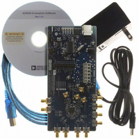
BOARD EVAL FOR AD9520-4
Manufacturer
Analog Devices Inc
Specifications of AD9520-4/PCBZ
Design Resources
Synchronizing Multiple AD9910 1 GSPS Direct Digital Synthesizers (CN0121) Phase Coherent FSK Modulator (CN0186)
Main Purpose
Timing, Clock Generator
Embedded
No
Utilized Ic / Part
AD9520-4
Primary Attributes
1.4 ~ 1.8 GHz Output Frequency
Secondary Attributes
Accepts CMOS, LVDS, or LVPECL References Up to 250 MHz
Silicon Manufacturer
Analog Devices
Application Sub Type
PLL Clock Synthesizer
Kit Application Type
Clock & Timing
Silicon Core Number
AD9520-0, AD9520-2, AD9520-2
Silicon Family Name
AD9520-X
Rohs Compliant
Yes
Lead Free Status / RoHS Status
Lead free / RoHS Compliant


UG-076
AD9520 BINARY FILE GENERATION
The AD9520 evaluation software can be used to generate binary
setup files that can be used by EEPROM programmers, such as
those made by BPM Microsystems.
Clicking Generate Binary File from the File menu prompts the
user to enter a filename. The .bin extension is assumed. There is
no facility for loading a .bin file into the software.
The binary file format is such that Byte Offset 0 in the binary
file contains the value for Register 0x000.
CHECKSUM GENERATION
Both 8-bit and 16-bit checksums are supported. The device
checksum is calculated using Address 0x00 through Address
0x232. The data pattern checksum uses Address 0x00 through
Address 0xB03.
The 8-bit checksum is an 8-bit sum of the byte range described
previously, whereas the 16-bit checksum forms a 16-bit word in
which the MSB is the odd register addresses, and the LSB is the
even-numbered registers. For example, Register 0x000 and
Register 0x001 are paired together prior to the summation
process.
The checksum values are also stored in the .stp files generated
by the evaluation software.
ESD CAUTION
Evaluation boards are only intended for device evaluation and not for production purposes. Evaluation boards are supplied “as is” and without warranties of any kind, express,
implied, or statutory including, but not limited to, any implied warranty of merchantability or fitness for a particular purpose. No license is granted by implication or otherwise under
any patents or other intellectual property by application or use of evaluation boards. Information furnished by Analog Devices is believed to be accurate and reliable. However, no
responsibility is assumed by Analog Devices for its use, nor for any infringements of patents or other rights of third parties that may result from its use. Analog Devices reserves the
right to change devices or specifications at any time without notice. Trademarks and registered trademarks are the property of their respective owners. Evaluation boards are not
authorized to be used in life support devices or systems.
©2010 Analog Devices, Inc. All rights reserved. Trademarks and
registered trademarks are the property of their respective owners.
UG08746-0-1/10(0)
Rev. 0 | Page 16 of 16
AVOIDING CHECKSUM MISMATCHES
It is possible to have differences in the setup and binary files
that may cause checksum mismatches. These scenarios are
outlined as follows.
The evaluation software automatically sets the VCO calibration
now bit (Register 0x018[0]) in the .bin file if the PLL is turned
on. If the VCO calibration now bit is not set, the AD9520 will
be unable to lock the PLL after automatically loading the register
values from the EEPROM without further user intervention.
Register 0x018[0] is not normally set in the register setup (.stp)
file because the user normally initiates VCO calibration manually
while running the evaluation software. To avoid a checksum
mismatch, it is recommended that the user manually set the
VCO calibration now bit in the setup file if the PLL is enabled.
Register 0x01F is a read-only status register whose value can
change in between the writing of the setup (.stp) file and the
binary (.bin) file. This situation is likely to occur if the reference
input frequency monitors are enabled and the reference inputs
are left floating. To prevent this, the user should avoid leaving
the reference inputs floating, or disconnect the evaluation board
while saving the setup and corresponding binary file.
Evaluation Board User Guide
Related parts for AD9520-4/PCBZ
Image
Part Number
Description
Manufacturer
Datasheet
Request
R

Part Number:
Description:
12/24 Channel Clock Gen 2,0GH
Manufacturer:
Analog Devices Inc
Datasheet:

Part Number:
Description:
12/24 Channel Clock Gen 2,0GH
Manufacturer:
Analog Devices Inc
Datasheet:
Part Number:
Description:
12/24 Channel Clock Gen 2,0GH
Manufacturer:
Analog Devices Inc
Datasheet:
Part Number:
Description:
12/24 Channel Clock Gen 2,0GH
Manufacturer:
Analog Devices Inc
Datasheet:
Part Number:
Description:
12/24 Channel Clock Gen 2,0GH
Manufacturer:
Analog Devices Inc
Datasheet:
Part Number:
Description:
Clock IC With 2.8GHz On-chip VCO
Manufacturer:
Analog Devices Inc
Datasheet:
Part Number:
Description:
Lock IC With 2.8GHz On-chip VCO
Manufacturer:
Analog Devices Inc
Datasheet:
Part Number:
Description:
12/24 Channel Clock Gen 2,5 GHz VCO
Manufacturer:
Analog Devices Inc
Datasheet:
Part Number:
Description:
12/24 Channel Clock Distribution W/ On-C
Manufacturer:
Analog Devices Inc
Datasheet:
Part Number:
Description:
12/24 Channel Clock Gen 2,25GH
Manufacturer:
Analog Devices Inc
Datasheet:
Part Number:
Description:
12/24 Channel Clock Distribution W/ On-C
Manufacturer:
Analog Devices Inc
Datasheet:
Part Number:
Description:
12/24 Channel Clock Distribution W/ On-C
Manufacturer:
Analog Devices Inc
Datasheet:
Part Number:
Description:
Clock IC With 1.6GHz On-chip VCO
Manufacturer:
Analog Devices Inc
Datasheet:
Part Number:
Description:
Clock IC With 1.6GHz On-chip VCO
Manufacturer:
Analog Devices Inc
Datasheet:
Part Number:
Description:
12/24-Output Clock Generator
Manufacturer:
Analog Devices Inc
Datasheet: