LMK03200EVAL National Semiconductor, LMK03200EVAL Datasheet - Page 36
LMK03200EVAL
Manufacturer Part Number
LMK03200EVAL
Description
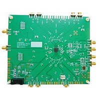
BOARD EVALUATION LMK03200
Manufacturer
National Semiconductor
Specifications of LMK03200EVAL
Main Purpose
Timing, Clock Conditioner
Embedded
No
Utilized Ic / Part
LMK03200
Primary Attributes
3 LVDS & 5 LVPECL Outputs, Integrated PLL & VCO
Secondary Attributes
3.15 V ~ 3.45 V Supply
Silicon Manufacturer
National
Silicon Core Number
LMK03200
Kit Application Type
Clock & Timing
Application Sub Type
Precision Clock Conditioner
Kit Contents
Board, Cable
Lead Free Status / RoHS Status
Lead free / RoHS Compliant


www.national.com
3.7.3 Termination for Single-Ended Operation
A balun can be used with either LVDS or LVPECL drivers to
convert the balanced, differential signal into an unbalanced,
single-ended signal.
It is possible to use an LVPECL driver as one or two separate
800 mV p-p signals. When DC coupling one of the LMK03200
family clock LVPECL drivers, the termination should still be
50 ohms to Vcc - 2 V as shown in
Thevenin equivalent circuit (120 Ω resistor connected to Vcc
and an 82 Ω resistor connected to ground with the driver con-
nected to the junction of the 120 Ω and 82 Ω resistors) is a
valid termination as shown in
FIGURE 13. Single-Ended LVPECL Operation, DC
FIGURE 14. Single-Ended LVPECL Operation, DC
Coupling, Thevenin Equivalent
Coupling
Figure 14
Figure
for Vcc = 3.3 V.
13. Again the
30088716
30088715
36
When AC coupling an LVPECL driver use a 120 Ω emitter
resistor to provide a DC path to ground and ensure a 50 ohm
termination with the proper DC bias level for the receiver. The
typical DC bias voltage for LVPECL receivers is 2 V (See
3.7.2). If the other driver is not used it should be terminated
with either a proper AC or DC termination. This latter example
of AC coupling a single-ended LVPECL signal can be used to
measure single-ended LVPECL performance using a spec-
trum analyzer or phase noise analyzer. When using most RF
test equipment no DC bias point (0 V DC) is expected for safe
and proper operation. The internal 50 ohm termination the test
equipment correctly terminates the LVPECL driver being
measured as shown in . When using only one LVPECL driver
of a CLKoutX/CLKoutX* pair, be sure to properly terminated
the unused driver.
3.7.4 Conversion to LVCMOS Outputs
To drive an LVCMOS input with an LMK03200 family LVDS
or LVPECL output, an LVPECL/LVDS to LVCMOS converter
such
DS90LV028A, DS90LV048A, etc. is required. For best noise
performance, LVPECL provides a higher voltage swing into
input of the converter.
3.8 OSCin INPUT
In addition to LVDS and LVPECL inputs, OSCin can also be
driven with a sine wave. The OSCin input can be driven sin-
gle-ended or differentially with sine waves. The configurations
for these are shown in
FIGURE 15. Single-Ended LVPECL Operation, AC
FIGURE 16. Single-Ended Sine Wave Input
as
National
Figure 16
Coupling
Semiconductor's
and
Figure
17.
DS90LV018A,
30088722
30088714
Related parts for LMK03200EVAL
Image
Part Number
Description
Manufacturer
Datasheet
Request
R

Part Number:
Description:
Precision 0-delay Clock Conditioner With Integrated Vco
Manufacturer:
National Semiconductor Corporation
Datasheet:

Part Number:
Description:
National Semiconductor [8-Bit D/A Converter]
Manufacturer:
National Semiconductor
Datasheet:
Part Number:
Description:
National Semiconductor [Media Coprocessor]
Manufacturer:
National Semiconductor
Datasheet:
Part Number:
Description:
Digitally Controlled Tone and Volume Circuit with Stereo Audio Power Amplifier, Microphone Preamp Stage and National 3D Sound
Manufacturer:
National Semiconductor
Datasheet:
Part Number:
Description:
Digitally Controlled Tone and Volume Circuit with Stereo Audio Power Amplifier, Microphone Preamp Stage and National 3D Sound
Manufacturer:
National Semiconductor
Datasheet:
Part Number:
Description:
AC97 Rev 2 Codec with Sample Rate Conversion and National 3D Sound
Manufacturer:
National Semiconductor
Part Number:
Description:
Manufacturer:
National Semiconductor
Datasheet:
Part Number:
Description:
Manufacturer:
National Semiconductor
Datasheet:
Part Number:
Description:
General Purpose, Low Voltage, Low Power, Rail-to-Rail Output Operational Amplifiers
Manufacturer:
National Semiconductor
Datasheet:
Part Number:
Description:
8-bit 20 MSPS flash A/D converter.
Manufacturer:
National Semiconductor
Datasheet:
Part Number:
Description:
Low Noise Quad Operational Amplifier
Manufacturer:
National Semiconductor
Datasheet:
Part Number:
Description:
Quad Differential Line Receivers
Manufacturer:
National Semiconductor
Datasheet:
Part Number:
Description:
Quad High Speed Trapezoidal? Bus Transceiver
Manufacturer:
National Semiconductor
Datasheet:
Part Number:
Description:
Dual Line Receiver
Manufacturer:
National Semiconductor
Datasheet: