SSM2315-EVALZ Analog Devices Inc, SSM2315-EVALZ Datasheet - Page 5
SSM2315-EVALZ
Manufacturer Part Number
SSM2315-EVALZ
Description
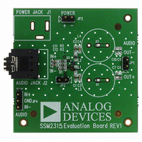
BOARD EVAL SSM2315
Manufacturer
Analog Devices Inc
Specifications of SSM2315-EVALZ
Amplifier Type
Class D
Output Type
1-Channel (Mono)
Max Output Power X Channels @ Load
4.28W x 1 @ 3 Ohm
Voltage - Supply
2.5 V ~ 5.5 V
Operating Temperature
-40°C ~ 85°C
Board Type
Fully Populated
Utilized Ic / Part
SSM2315
Silicon Manufacturer
Analog Devices
Application Sub Type
Audio Power Amplifier - Class D
Kit Application Type
Amplifier
Silicon Core Number
SSM2315
Kit Contents
Board
Lead Free Status / RoHS Status
Lead free / RoHS Compliant


Component Placement and Clearance
Place all related components except decoupling capacitors on
the same side as the SSM2315 and as close as possible to the
chip to avoid vias (see Figure 5).
Place decoupling capacitors on the bottom side and close to the
GND pin (see Figure 7).
Top Layer Copper Land and Ground Pouring
The output peak current of this amplifier is more than 1 A;
therefore, PCB traces should be wide (>2 mm) to handle the
high current. For the best performance, use symmetrical copper
lands as large as space allows (instead of traces) for the output
pins (see Figure 3).
Pour ground copper on the top side and use many vias to connect
the top layer ground copper to the dedicated ground plane. The
copper pouring on the top layer serves as both the EMI shielding
ground plane and the heat sink for the SSM2315.
The SSM2315 works well only if these techniques are implemented
in the PCB design to keep EMI and the amplifier temperature low.
Rev. 0 | Page 5 of 12
GETTING STARTED
To ensure proper operation, carefully follow Step 1 through Step 4.
1.
2.
3.
4.
WHAT TO TEST
When implementing the SSM2315 evaluation board, test the
board for the following items:
•
•
•
•
•
•
If a jumper is on JP2, remove the jumper to turn on the
amplifier.
Connect the load to the audio output connector, JP1.
Connect the audio input to the board, either in differential
mode or single-ended mode, depending on the application.
Connect the power supply with the proper polarity and
voltage.
Electromagnetic interference (EMI)—connect wires for the
speakers, making sure they are the same length as the wires
required for the actual application environment; then com-
plete the EMI test.
Signal-to-noise ratio (SNR).
Output noise—use an A-weighted filter to filter the output
before reading the measurement meter.
Maximum output power.
Distortion.
Efficiency.
EVAL-SSM2315
Related parts for SSM2315-EVALZ
Image
Part Number
Description
Manufacturer
Datasheet
Request
R

Part Number:
Description:
±1.7g Dual-Axis IMEMS Accelerometer Evaluation Board
Manufacturer:
Analog Devices Inc
Datasheet:

Part Number:
Description:
Inertial Sensor Evaluation System
Manufacturer:
Analog Devices Inc
Datasheet:
Part Number:
Description:
Manufacturer:
Analog Devices Inc
Datasheet:
Part Number:
Description:
Manufacturer:
Analog Devices Inc
Datasheet:
Part Number:
Description:
Manufacturer:
Analog Devices Inc
Datasheet:
Part Number:
Description:
Manufacturer:
Analog Devices Inc
Datasheet:
Part Number:
Description:
Manufacturer:
Analog Devices Inc
Datasheet:
Part Number:
Description:
Manufacturer:
Analog Devices Inc
Datasheet:
Part Number:
Description:
Manufacturer:
Analog Devices Inc
Datasheet:
Part Number:
Description:
Manufacturer:
Analog Devices Inc
Datasheet:
Part Number:
Description:
Manufacturer:
Analog Devices Inc
Datasheet:
Part Number:
Description:
Manufacturer:
Analog Devices Inc
Datasheet:
Part Number:
Description:
Manufacturer:
Analog Devices Inc
Datasheet: