DAK-85 Power Integrations, DAK-85 Datasheet - Page 3
DAK-85
Manufacturer Part Number
DAK-85
Description
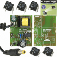
DESIGN ACCELERATOR KIT LP SWITCH
Manufacturer
Power Integrations
Series
LinkSwitch®-LPr
Specifications of DAK-85
Main Purpose
AC/DC, Primary Side
Outputs And Type
1, Isolated
Power - Output
2W
Voltage - Output
6V
Current - Output
330mA
Voltage - Input
90 ~ 265VAC
Regulator Topology
Flyback
Frequency - Switching
66kHz
Board Type
Bare (Unpopulated) and Fully Populated
Utilized Ic / Part
LNK562, LNK563, LNK564
Lead Free Status / RoHS Status
Lead free / RoHS Compliant
Other names
596-1104
Available stocks
Company
Part Number
Manufacturer
Quantity
Price
Company:

Part Number:
DAK-85
Manufacturer:
Power Integrations
Quantity:
135


Table of Contents
1
2
3
4
5
6
7
8
9
10
11
12
13
Important Note:
Although this board is designed to satisfy safety isolation requirements, the engineering
prototype has not been agency approved. Therefore, all testing should be performed
using an isolation transformer to provide the AC input to the prototype board.
Page 3 of 32
4.1
4.2
4.3
4.4
4.5
7.1
7.2
7.3
7.4
7.5
8.1
8.2
8.3
10.1
10.2
10.3
10.4
Introduction .................................................................................................................4
Power Supply Specification ........................................................................................6
Schematic ...................................................................................................................7
Circuit Description.......................................................................................................7
PCB Layout.................................................................................................................9
Bill Of Materials.........................................................................................................10
Transformer Specification .........................................................................................11
Performance Data.....................................................................................................16
8.1.1
Thermal Performance ...............................................................................................18
10.4.1
10.4.2
Waveforms ............................................................................................................20
Conducted EMI .....................................................................................................25
AC Line Surge.......................................................................................................27
Revision History ....................................................................................................28
Input and EMI Filtering.........................................................................................7
LinkSwitch-LP Feedback .....................................................................................7
Primary Clamp and Transformer Construction ....................................................8
Output Rectification and Filtering.........................................................................8
Optional Components ..........................................................................................8
Electrical Diagram..............................................................................................11
Electrical Specifications .....................................................................................11
Materials ............................................................................................................12
Transformer Build Diagram................................................................................12
Design Spreadsheet ..........................................................................................14
Efficiency ...........................................................................................................16
No-Load Input Power.........................................................................................17
Regulation .........................................................................................................17
Drain Voltage and Current, Normal Operation...................................................20
Output Voltage Start-Up Profile, Battery Load ...................................................21
Drain Voltage and Current Start-Up Profile........................................................22
Output Ripple Measurements ............................................................................23
Active Mode CEC Measurement Data........................................................16
Ripple Measurement Technique.................................................................23
Measurement Results.................................................................................24
Tel: +1 408 414 9200 Fax: +1 408 414 9201
Power Integrations
www.powerint.com
Related parts for DAK-85
Image
Part Number
Description
Manufacturer
Datasheet
Request
R

Part Number:
Description:
KIT DESIGN ACCELERATOR MODEM
Manufacturer:
Power Integrations
Datasheet:

Part Number:
Description:
KIT DESIGN ACCELERATOR SET TOP
Manufacturer:
Power Integrations
Datasheet:

Part Number:
Description:
KIT REF DES DPA 6.6W DC-DC CONV
Manufacturer:
Power Integrations
Datasheet:

Part Number:
Description:
KIT DESIGN ACCELERATOR POE CONV
Manufacturer:
Power Integrations
Datasheet:

Part Number:
Description:
DESIGN ACCELERATOR KIT XT SWITCH
Manufacturer:
Power Integrations
Datasheet:

Part Number:
Description:
KIT DESIGN ACC PEAKSWITCH FAMILY
Manufacturer:
Power Integrations
Datasheet:

Part Number:
Description:
KIT DESIGN ACCELERATOR ADAPTER
Manufacturer:
Power Integrations
Datasheet:

Part Number:
Description:
KIT DESIGN ACCELERATOR ADAPTER
Manufacturer:
Power Integrations
Datasheet:

Part Number:
Description:
KIT DESIGN ACCELERATOR DC-DC
Manufacturer:
Power Integrations
Datasheet:

Part Number:
Description:
KIT DESIGN ACCELERATOR DPA SW
Manufacturer:
Power Integrations
Datasheet: