DAK-85 Power Integrations, DAK-85 Datasheet - Page 7
DAK-85
Manufacturer Part Number
DAK-85
Description
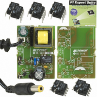
DESIGN ACCELERATOR KIT LP SWITCH
Manufacturer
Power Integrations
Series
LinkSwitch®-LPr
Specifications of DAK-85
Main Purpose
AC/DC, Primary Side
Outputs And Type
1, Isolated
Power - Output
2W
Voltage - Output
6V
Current - Output
330mA
Voltage - Input
90 ~ 265VAC
Regulator Topology
Flyback
Frequency - Switching
66kHz
Board Type
Bare (Unpopulated) and Fully Populated
Utilized Ic / Part
LNK562, LNK563, LNK564
Lead Free Status / RoHS Status
Lead free / RoHS Compliant
Other names
596-1104
Available stocks
Company
Part Number
Manufacturer
Quantity
Price
Company:

Part Number:
DAK-85
Manufacturer:
Power Integrations
Quantity:
135


04-Oct-2005
EP-85 6 V, 330 mA Low Cost Charger
3 Schematic
Figure 3 – LNK564 Low Cost Charger Schematic.
4 Circuit Description
4.1 Input and EMI Filtering
AC input differential filtering is accomplished with the very low cost input filter stage
formed by C1 and L1. The proprietary frequency jitter feature of the LNK564 eliminates
the need for an input pi filter, so only a single bulk capacitor is required. This allows the
input inductor L1 to be used as a fuse as well as a filter component. This very simple
Filterfuse input stage further reduces system cost. The L1 is sleeved to allow it to function
as a fuse. An optional fusible resistor, RF1, may be used to provide the fusing function.
Input diode D2 may be removed from the neutral phase in applications where decreased
EMI margins and/or decreased input surge withstand is allowed.
4.2 LinkSwitch-LP Feedback
The power supply utilizes simplified bias winding voltage feedback enabled by LNK564
ON/OFF control. The resistor divider formed by R1 and R2 determine the output voltage
across the transformer bias winding during the switch off time. In the V/I constant voltage
region, the LNK564 device enables/disables switching cycles to maintain 1.69 V on the
FB pin. Diode D3 and low cost ceramic capacitor C3 provide rectification and filtering of
the primary feedback winding waveform. At increased loads, beyond the constant power
threshold, the FB pin voltage begins to reduce as the power supply output voltage falls.
The internal oscillator frequency is linearly reduced in this region until it reaches typically
50% of the starting frequency when the FB pin voltage reaches the auto-restart threshold
voltage (typically 0.8 V on the FB pin, which is equivalent to 1 V to 1.5 V at the output of
the power supply). This function limits the output current in this region without fold back
until the output voltage is low.
Power Integrations
Tel: +1 408 414 9200 Fax: +1 408 414 9201
Page 7 of 32
www.powerint.com
Related parts for DAK-85
Image
Part Number
Description
Manufacturer
Datasheet
Request
R

Part Number:
Description:
KIT DESIGN ACCELERATOR MODEM
Manufacturer:
Power Integrations
Datasheet:

Part Number:
Description:
KIT DESIGN ACCELERATOR SET TOP
Manufacturer:
Power Integrations
Datasheet:

Part Number:
Description:
KIT REF DES DPA 6.6W DC-DC CONV
Manufacturer:
Power Integrations
Datasheet:

Part Number:
Description:
KIT DESIGN ACCELERATOR POE CONV
Manufacturer:
Power Integrations
Datasheet:

Part Number:
Description:
DESIGN ACCELERATOR KIT XT SWITCH
Manufacturer:
Power Integrations
Datasheet:

Part Number:
Description:
KIT DESIGN ACC PEAKSWITCH FAMILY
Manufacturer:
Power Integrations
Datasheet:

Part Number:
Description:
KIT DESIGN ACCELERATOR ADAPTER
Manufacturer:
Power Integrations
Datasheet:

Part Number:
Description:
KIT DESIGN ACCELERATOR ADAPTER
Manufacturer:
Power Integrations
Datasheet:

Part Number:
Description:
KIT DESIGN ACCELERATOR DC-DC
Manufacturer:
Power Integrations
Datasheet:

Part Number:
Description:
KIT DESIGN ACCELERATOR DPA SW
Manufacturer:
Power Integrations
Datasheet: