STEVAL-ISA035V1 STMicroelectronics, STEVAL-ISA035V1 Datasheet
STEVAL-ISA035V1
Specifications of STEVAL-ISA035V1
Available stocks


Related parts for STEVAL-ISA035V1


STEVAL-ISA035V1 Summary of contents
Page 1
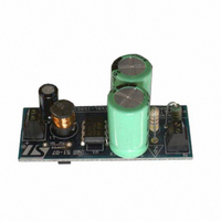
... About 200 mW at no-load consumption ■ Efficiency measured between 70% to 80% at full load ■ Integrated Short circuit protection Figure 1. Evaluation board (STEVAL-ISA035V1) Table 1. Operating conditions for the four samples Board version (with changes) Input voltage range Input voltage frequency range Output version 1 ...
Page 2
Contents Contents 1 Circuit operation . . . . . . . . . . . . . . . . . . . . . . . . . . . . . . . . . . . ...
Page 3
... AN2544 List of figures Figure 1. Evaluation board (STEVAL-ISA035V1 Figure 2. Inductor current: 470 µH VS 1000 µ Figure 3. Schematic for 350 Figure 4. Schematic for 350 Figure 5. Composite Figure 6. Top side . . . . . . . . . . . . . . . . . . . . . . . . . . . . . . . . . . . . . . . . . . . . . . . . . . . . . . . . . . . . . . . . 9 Figure 7. Bottom side and surface mount components (viewed from top Figure 8. Bad start . . . . . . . . . . . . . . . . . . . . . . . . . . . . . . . . . . . . . . . . . . . . . . . . . . . . . . . . . . . . . . . 11 Figure 9. ...
Page 4
Circuit operation 1 Circuit operation 1.1 Input line rectification and line conducted filter The circuit operations for all four versions are basically the same. The difference is in the circuit for startup. Version 1 will be described here with reference ...
Page 5
AN2544 1.3 Inductor selection A starting point for the inductor operating in discontinuous mode can be derived from the following formula which gives a good approximation of the inductor. Equation 1 Where Id is the minimum peak drain current, 320 ...
Page 6
Circuit operation Figure 2. Inductor current: 470 µH VS 1000 µH The blue trace is the current with 470 µH inductor and the purple trace is the current with a 1000 µH inductor. On the above scope plot in inductor. ...
Page 7
AN2544 Figure 3. Schematic for 350 mA Fb Source 3 2 Source 1 Drain 5 Drain 6 Vdd Drain 4 7 Drain 8 Circuit operation 7/17 ...
Page 8
Circuit operation Figure 4. Schematic for 350 mA 8/17 Fb Source 3 2 Source 1 Drain 5 Drain 6 Vdd Drain 4 7 Drain 8 AN2544 ...
Page 9
AN2544 1.6 Board layout A composite view of the board shows a double-sided board with surface mount components on the bottom. The top is a ground plane which helps with EMI. The actual measurements of the PC board are 55 ...
Page 10
... Vf can share the same source without dd CAT Ceramic UCC EKMG401ELL100MJ20S TDK C3216X7R1E475K TDK C2012X7R1E474K Low ESR Murata GRM55DR73A104KW011 BZT5212FDICT BZT5216FDICT S1MD STMicroelectronics Mouser 651-1751099 JW Miller 5300-33 Compostar Q3277 or JW Miller RL895-102K ALSR1J- 1206 CERAMIC STMicroelectronics S1MD X7R +/-10% TDK C2012X7R1E474K 24 AWG AN2544 pin-for- ...
Page 11
AN2544 The VIPer internal 1 mA current source charges up the V the V pin reaches the V dd raising the output voltage to the point of bootstrapping. The V the energy to supply the necessary output current and to ...
Page 12
Circuit operation Figure 10. Burst mode 1.8 Short circuit The VIPer has pulse-by-pulse current limit. When the current ramps up to the current limit, the pulse is terminated. This is manifested by reducing the output voltage as the current is ...
Page 13
AN2544 1.9 Performance Regulation for the VIPer22A-E and VIPer12A-E can be seen below. Keep in mind that the buck topology will peak charge at zero load. DZ1 will clamp the voltage above the output. Load ...
Page 14
Circuit operation Table 6. VIPer12ADIP- 200 mA (continued) Vin Ripple Blue Angel at no-load at 115 V Short circuit 12 V output load regulation for VIPer12-E and VIPer22A-E is shown in Figure 12. Load regulations for 12 ...
Page 15
AN2544 Figure 14. Efficiency Efficiency is about 75% at 120 V 1.10 EMI conducted EMI was checked for all four versions for maximum peak reading. Figure 15. VIPer22- 350 mA output Efficiency VS Input Line for 12V ...
Page 16
Conclusion Figure 17. VIPer22- 350 mA output 2 Conclusion Using the VIPer in the buck mode has its benefits for appliances and other industrial equipment which require a reference to neutral. For currents up to 350 mA ...
Page 17
... AN2544 Information in this document is provided solely in connection with ST products. STMicroelectronics NV and its subsidiaries (“ST”) reserve the right to make changes, corrections, modifications or improvements, to this document, and the products and services described herein at any time, without notice. All ST products are sold pursuant to ST’s terms and conditions of sale. ...