STEVAL-ISA035V1 STMicroelectronics, STEVAL-ISA035V1 Datasheet - Page 5
STEVAL-ISA035V1
Manufacturer Part Number
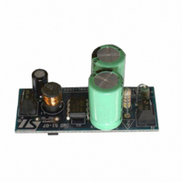
STEVAL-ISA035V1
Description
BOARD EVAL BASED ON VIPER22A
Manufacturer
STMicroelectronics
Series
VIPER™r
Type
Other Power Managementr
Specifications of STEVAL-ISA035V1
Mfg Application Notes
VIPer12/22A-E AppNote
Main Purpose
AC/DC, Non-Isolated
Outputs And Type
1, Non-Isolated
Power - Output
4.2W
Voltage - Output
12V
Current - Output
350mA
Voltage - Input
85 ~ 264VAC
Regulator Topology
Buck
Frequency - Switching
60kHz
Board Type
Fully Populated
Utilized Ic / Part
VIPer22A
Input Voltage
85 V to 264 V
Output Voltage
12 V
Product
Power Management Modules
Lead Free Status / RoHS Status
Lead free / RoHS Compliant
For Use With/related Products
VIPER22A-E
Other names
497-8215
Available stocks
Company
Part Number
Manufacturer
Quantity
Price
Company:

Part Number:
STEVAL-ISA035V1
Manufacturer:
STMicroelectronics
Quantity:
1


AN2544
1.3
1.4
1.5
Inductor selection
A starting point for the inductor operating in discontinuous mode can be derived from the
following formula which gives a good approximation of the inductor.
Equation 1
Where Id
the VIPer22A-E, f is the switching frequency at 60 kHz. The maximum peak current limits
the power delivered in the buck topology. Therefore, the calculation above is for an inductor
that operates in discontinuous mode. If the current swings down to zero, than the peak
current is twice the output. This limits the output current to 280 mA for a VIPer22A-E. If the
inductor is a larger value, operating between continuous and discontinuous mode, we can
reach 200 mA comfortably away from the current limit point. C6 has to be a low ESR
capacitor to give the low ripple voltage
Equation 2
D5 needs to be a fast recovery diode but D6 and D8 can be standard diodes. DZ1 is used to
clamp the voltage to 16 V. The nature of the buck topology is to peak charge at no-load. A
Zener 3 to 4 V higher than the output voltage is recommended.
Design example
Figure 3
current of 350 mA. If less current is required, then the VIPer22A-E can be changed to a
VIPer12A-E and C2 can be decreased from 10 µf to 4.7 µF. This delivers up to 200 mA.
Figure 4
jumper bridges the output voltage to the V
Design hints and trade-off
The value of L determines the boundary condition between continuous and discontinuous
mode for a given output current. In order to operate in discontinuous mode, the inductor
value has to be lower than
Equation 3
Where R is the load resistance, T is the switching period, and D is the duty cycle.
There are two points to consider. One is, the more discontinuous the higher the peak
current. This point should be kept lower than the minimum pulse by pulse current limit of the
VIPer22A-E which is 0.56 A. The other is if we use a larger value inductor to run continuous
all of the time, we run into excess heat from switching losses of the MOSFET inside the
VIPer. Of course, the inductor current rating must be higher than the output current to
prevent the risk of saturating the core.
shows the same board but for 16 V output or higher, D6 and C4 can be left out. The
is the schematic for the evaluation board. It is set up for 12 V with a maximum
peak
is the minimum peak drain current, 320 mA for the VIPer12A-E and 560 mA for
V
L
L
ripple
=
=
1
-- -
2
2
•
=
dd
•
R T
------------------------------- -
(
I
pin.
Id
ripple
•
peak
Pout
•
•
(
)
1 D
2
Cesr
–
•
f
)
Circuit operation
5/17
Related parts for STEVAL-ISA035V1
Image
Part Number
Description
Manufacturer
Datasheet
Request
R

Part Number:
Description:
BOARD RGB CTR ST7,STP08C596MTR
Manufacturer:
STMicroelectronics
Datasheet:

Part Number:
Description:
Power Management IC Development Tools Full Speed USB to RS232 Bridge Demo
Manufacturer:
STMicroelectronics
Datasheet:
Part Number:
Description:
Power Management IC Development Tools 2.5W solar eval BRD USB SPV1040 LD39050
Manufacturer:
STMicroelectronics
Datasheet:

Part Number:
Description:
BOARD EVAL FOR MEMS SENSORS
Manufacturer:
STMicroelectronics
Datasheet:

Part Number:
Description:
KIT DEV STARTER ST10F276Z5
Manufacturer:
STMicroelectronics
Datasheet:

Part Number:
Description:
BOARD EVAL HDMI $ VIDEO SWITCH
Manufacturer:
STMicroelectronics
Datasheet:

Part Number:
Description:
BOARD DEMO ACCELEROMETER DIL24
Manufacturer:
STMicroelectronics
Datasheet:

Part Number:
Description:
BOARD STLM75/STDS75/ST72F651
Manufacturer:
STMicroelectronics
Datasheet:

Part Number:
Description:
EVAL BOARD 3AXIS MEMS ACCELLRMTR
Manufacturer:
STMicroelectronics
Datasheet:

Part Number:
Description:
BOARD EVAL 8BIT MICRO + TDE1708
Manufacturer:
STMicroelectronics
Datasheet:
Part Number:
Description:
STMicroelectronics [RIPPLE-CARRY BINARY COUNTER/DIVIDERS]
Manufacturer:
STMicroelectronics
Datasheet:
Part Number:
Description:
STMicroelectronics [LIQUID-CRYSTAL DISPLAY DRIVERS]
Manufacturer:
STMicroelectronics
Datasheet:
Part Number:
Description:
BOARD EVAL FOR MEMS SENSORS
Manufacturer:
STMicroelectronics
Datasheet: