STEVAL-ISA052V2 STMicroelectronics, STEVAL-ISA052V2 Datasheet - Page 35
STEVAL-ISA052V2
Manufacturer Part Number
STEVAL-ISA052V2
Description
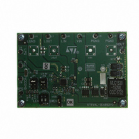
BOARD EVAL BASED ON PM6675A
Manufacturer
STMicroelectronics
Type
DC/DC Switching Converters, Regulators & Controllersr
Specifications of STEVAL-ISA052V2
Design Resources
STEVAL-ISA052V2 Gerber Files STEVAL-ISA052V2 Schematic STEVAL-ISA052V2 Bill of Material
Main Purpose
DC/DC, Step Down with LDO
Outputs And Type
2, Non-Isolated
Voltage - Output
1.5V, 0.6 ~ 3.3V
Voltage - Input
4.5 ~ 36 V
Regulator Topology
Buck
Board Type
Fully Populated
Utilized Ic / Part
PM6675AS
Input Voltage
4.5 V to 36 V
Output Voltage
1.5 V
Product
Power Management Modules
Lead Free Status / RoHS Status
Lead free / RoHS Compliant
Current - Output
-
Power - Output
-
Frequency - Switching
-
Lead Free Status / Rohs Status
Supplier Unconfirmed
For Use With/related Products
PM6675AS
Other names
497-8413
Available stocks
Company
Part Number
Manufacturer
Quantity
Price
Company:

Part Number:
STEVAL-ISA052V2
Manufacturer:
STMicroelectronics
Quantity:
1


PM6675AS
8.1.1
Equation 28 a
Equation 28 b
Referring to the typical application schematic (figs. 1 and 23), the final expression is then:
Equation 29
Even if the switching frequency is theoretically independent from battery and output
voltages, parasitic parameters involved in power path (like MOSFETs on-resistance and
inductor DCR) introduce voltage drops responsible of a slight dependence on load current.
In addition, the internal delay is cause of a light dependence from input voltage.
Table 10.
Inductor selection
Once the switching frequency has been defined, the inductance value depends on the
desired inductor ripple current. Low inductance value means great ripple current that brings
to poor efficiency and great output noise. On the other hand a great current ripple is
desirable for fast transient response when a load step is applied.
Otherwise, great inductance brings to good efficiency but the transient response is critical,
especially if V
assure system stability and jitter-free operations (see Output capacitor selection paragraph).
The product of the output capacitor ESR multiplied by the inductor ripple current must be
taken into consideration. A good trade-off between the transient response time, the
efficiency, the cost and the size is to choose the inductance value in order to maintain the
inductor ripple current between 20 % and 50 % (usually 40 %) of the maximum output
current.
The maximum inductor ripple current, ∆I
R1 (kΩ)
330
330
330
330
330
330
Typical values for switching frequency selection
INmin
- V
out
is little. Moreover a minimum output ripple voltage is necessary to
f
SW
=
R2 (kΩ)
K
α
11
13
15
18
20
22
α
α
OSC
OSC
LMAX
OSC
OUT
=
=
=
, occurs at the maximum input voltage.
R
V
1
V
V
R
V
OUT
+
OSC
SNS
IN
2
R
2
⋅
K
Approx switching frequency (kHz)
OSC
1
Application information
250
300
350
400
450
500
35/48
Related parts for STEVAL-ISA052V2
Image
Part Number
Description
Manufacturer
Datasheet
Request
R

Part Number:
Description:
BOARD RGB CTR ST7,STP08C596MTR
Manufacturer:
STMicroelectronics
Datasheet:

Part Number:
Description:
Power Management IC Development Tools Full Speed USB to RS232 Bridge Demo
Manufacturer:
STMicroelectronics
Datasheet:
Part Number:
Description:
Power Management IC Development Tools 2.5W solar eval BRD USB SPV1040 LD39050
Manufacturer:
STMicroelectronics
Datasheet:

Part Number:
Description:
BOARD EVAL FOR MEMS SENSORS
Manufacturer:
STMicroelectronics
Datasheet:

Part Number:
Description:
KIT DEV STARTER ST10F276Z5
Manufacturer:
STMicroelectronics
Datasheet:

Part Number:
Description:
BOARD EVAL HDMI $ VIDEO SWITCH
Manufacturer:
STMicroelectronics
Datasheet:

Part Number:
Description:
BOARD DEMO ACCELEROMETER DIL24
Manufacturer:
STMicroelectronics
Datasheet:

Part Number:
Description:
BOARD STLM75/STDS75/ST72F651
Manufacturer:
STMicroelectronics
Datasheet:

Part Number:
Description:
EVAL BOARD 3AXIS MEMS ACCELLRMTR
Manufacturer:
STMicroelectronics
Datasheet:

Part Number:
Description:
BOARD EVAL 8BIT MICRO + TDE1708
Manufacturer:
STMicroelectronics
Datasheet:
Part Number:
Description:
STMicroelectronics [RIPPLE-CARRY BINARY COUNTER/DIVIDERS]
Manufacturer:
STMicroelectronics
Datasheet:
Part Number:
Description:
STMicroelectronics [LIQUID-CRYSTAL DISPLAY DRIVERS]
Manufacturer:
STMicroelectronics
Datasheet:
Part Number:
Description:
BOARD EVAL FOR MEMS SENSORS
Manufacturer:
STMicroelectronics
Datasheet: