EVAL5985 STMicroelectronics, EVAL5985 Datasheet - Page 14
EVAL5985
Manufacturer Part Number
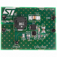
EVAL5985
Description
BOARD EVAL FOR L5985
Manufacturer
STMicroelectronics
Type
DC/DC Switching Converters, Regulators & Controllersr
Specifications of EVAL5985
Main Purpose
DC/DC, Step Down
Outputs And Type
1, Non-Isolated
Voltage - Output
3.3V
Current - Output
2A
Voltage - Input
3.3 ~ 18V
Regulator Topology
Buck
Frequency - Switching
500kHz
Board Type
Fully Populated
Utilized Ic / Part
L5985
Input Voltage
2.9 V to 18 V
Output Voltage
0.6 V to 16 V
Product
Power Management Modules
Silicon Manufacturer
ST Micro
Silicon Core Number
L5985
Kit Application Type
Power Management - Voltage Regulator
Application Sub Type
Step Down Switching Regulator
Kit Contents
Board
Lead Free Status / RoHS Status
Lead free / RoHS Compliant
Power - Output
-
Lead Free Status / Rohs Status
Lead free / RoHS Compliant
For Use With/related Products
L5985
Other names
497-6387
EVAL5985
EVAL5985
Available stocks
Company
Part Number
Manufacturer
Quantity
Price


Application information
5
5.1
14/37
Application information
Input capacitor selection
The capacitor connected to the input has to be capable to support the maximum input
operating voltage and the maximum RMS input current required by the device. The input
capacitor is subject to a pulsed current, the RMS value of which is dissipated over its ESR,
affecting the overall system efficiency.
So the input capacitor must have a RMS current rating higher than the maximum RMS input
current and an ESR value compliant with the expected efficiency.
The maximum RMS input current flowing through the capacitor can be calculated as:
Equation 3
Where Io is the maximum DC output current, D is the duty cycle, η is the efficiency.
Considering η = 1, this function has a maximum at D = 0.5 and it is equal to Io/2.
In a specific application the range of possible duty cycles has to be considered in order to
find out the maximum RMS input current. The maximum and minimum duty cycles can be
calculated as:
Equation 4
and
Equation 5
Where V
the internal PDMOS.
In
Table 6.
Table 6
Manufacturer
MURATA
F
TDK
some multi layer ceramic capacitors suitable for this device are reported:
is the forward voltage on the freewheeling diode and V
Input capacitors
Doc ID 13006 Rev 5
GRM31
GRM55
Series
C3225
I
RMS
D
D
MAX
MIN
=
I
=
O
=
⋅
------------------------------------- -
V
------------------------------------ -
V
INMAX
V
V
INMIN
D
OUT
OUT
–
2 D
-------------- -
+
Cap value (μF)
⋅
+
–
–
η
V
V
V
V
2
F
SW
SW
F
+
D
------ -
η
10
10
10
2
2
SW
is voltage drop across
Rated voltage (V)
25
25
25
L5985
Related parts for EVAL5985
Image
Part Number
Description
Manufacturer
Datasheet
Request
R

Part Number:
Description:
STMicroelectronics [RIPPLE-CARRY BINARY COUNTER/DIVIDERS]
Manufacturer:
STMicroelectronics
Datasheet:
Part Number:
Description:
STMicroelectronics [LIQUID-CRYSTAL DISPLAY DRIVERS]
Manufacturer:
STMicroelectronics
Datasheet:

Part Number:
Description:
BOARD EVAL FOR MEMS SENSORS
Manufacturer:
STMicroelectronics
Datasheet:
Part Number:
Description:
NPN TRANSISTOR POWER MODULE
Manufacturer:
STMicroelectronics
Datasheet:
Part Number:
Description:
TURBOSWITCH ULTRA-FAST HIGH VOLTAGE DIODE
Manufacturer:
STMicroelectronics
Datasheet:
Part Number:
Description:
Manufacturer:
STMicroelectronics
Datasheet:
Part Number:
Description:
DIODE / SCR MODULE
Manufacturer:
STMicroelectronics
Datasheet:
Part Number:
Description:
DIODE / SCR MODULE
Manufacturer:
STMicroelectronics
Datasheet:
Part Number:
Description:
Search -----> STE16N100
Manufacturer:
STMicroelectronics
Datasheet:
Part Number:
Description:
Search ---> STE53NA50
Manufacturer:
STMicroelectronics
Datasheet:
Part Number:
Description:
NPN Transistor Power Module
Manufacturer:
STMicroelectronics
Datasheet:
Part Number:
Description:
DIODE / SCR MODULE
Manufacturer:
STMicroelectronics
Datasheet: