EVAL5985 STMicroelectronics, EVAL5985 Datasheet - Page 3
EVAL5985
Manufacturer Part Number
EVAL5985
Description
BOARD EVAL FOR L5985
Manufacturer
STMicroelectronics
Type
DC/DC Switching Converters, Regulators & Controllersr
Specifications of EVAL5985
Main Purpose
DC/DC, Step Down
Outputs And Type
1, Non-Isolated
Voltage - Output
3.3V
Current - Output
2A
Voltage - Input
3.3 ~ 18V
Regulator Topology
Buck
Frequency - Switching
500kHz
Board Type
Fully Populated
Utilized Ic / Part
L5985
Input Voltage
2.9 V to 18 V
Output Voltage
0.6 V to 16 V
Product
Power Management Modules
Silicon Manufacturer
ST Micro
Silicon Core Number
L5985
Kit Application Type
Power Management - Voltage Regulator
Application Sub Type
Step Down Switching Regulator
Kit Contents
Board
Lead Free Status / RoHS Status
Lead free / RoHS Compliant
Power - Output
-
Lead Free Status / Rohs Status
Lead free / RoHS Compliant
For Use With/related Products
L5985
Other names
497-6387
EVAL5985
EVAL5985
Available stocks
Company
Part Number
Manufacturer
Quantity
Price


L5985
1
1.1
1.2
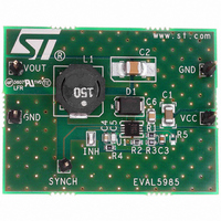
Pin settings
Pin connection
Figure 2.
Pin description
Table 1.
N°
1
2
3
4
5
6
7
8
Pin connection (top view)
Pin description
SYNCH
COMP
Type
GND
OUT
F
V
INH
FB
SW
CC
Regulator output
Master/slave synchronization. When it is left floating, a signal with a
phase shift of half a period respect to the power turn on is present at the
pin. When connected to an external signal at a frequency higher than the
internal one, then the device is synchronized by the external signal, with
zero phase shift.
Connecting together the SYNCH pin of two devices, the one with higher
frequency works as master and the other one as slave; so the two power
turn on have a phase shift of half a period.
A logical signal (active high) disable the device. With INH higher than
1.9 V the device is OFF and with INH lower than 0.6 V the device is ON.
Error amplifier output to be used for loop frequency compensation
Feedback input. Connecting the output voltage directly to this pin the
output voltage is regulated at 0.6 V. To have higher regulated voltages an
external resistor divider is required from Vout to FB pin.
The switching frequency can be increased connecting an external
resistor from FSW pin and ground. If this pin is left floating the deice
works at its free-running frequency of 250 kHz.
Ground
Unregulated DC input voltage
SYNCH
SYNCH
COMP
COMP
OUT
OUT
Doc ID 13006 Rev 5
INH
INH
Description
FB
FB
V
V
GND
GND
FSW
FSW
CC
CC
Pin settings
3/37
Related parts for EVAL5985
Image
Part Number
Description
Manufacturer
Datasheet
Request
R

Part Number:
Description:
STMicroelectronics [RIPPLE-CARRY BINARY COUNTER/DIVIDERS]
Manufacturer:
STMicroelectronics
Datasheet:
Part Number:
Description:
STMicroelectronics [LIQUID-CRYSTAL DISPLAY DRIVERS]
Manufacturer:
STMicroelectronics
Datasheet:

Part Number:
Description:
BOARD EVAL FOR MEMS SENSORS
Manufacturer:
STMicroelectronics
Datasheet:
Part Number:
Description:
NPN TRANSISTOR POWER MODULE
Manufacturer:
STMicroelectronics
Datasheet:
Part Number:
Description:
TURBOSWITCH ULTRA-FAST HIGH VOLTAGE DIODE
Manufacturer:
STMicroelectronics
Datasheet:
Part Number:
Description:
Manufacturer:
STMicroelectronics
Datasheet:
Part Number:
Description:
DIODE / SCR MODULE
Manufacturer:
STMicroelectronics
Datasheet:
Part Number:
Description:
DIODE / SCR MODULE
Manufacturer:
STMicroelectronics
Datasheet:
Part Number:
Description:
Search -----> STE16N100
Manufacturer:
STMicroelectronics
Datasheet:
Part Number:
Description:
Search ---> STE53NA50
Manufacturer:
STMicroelectronics
Datasheet:
Part Number:
Description:
NPN Transistor Power Module
Manufacturer:
STMicroelectronics
Datasheet:
Part Number:
Description:
DIODE / SCR MODULE
Manufacturer:
STMicroelectronics
Datasheet: