EVAL5985 STMicroelectronics, EVAL5985 Datasheet - Page 16
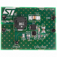
EVAL5985
Manufacturer Part Number
EVAL5985
Description
BOARD EVAL FOR L5985
Manufacturer
STMicroelectronics
Type
DC/DC Switching Converters, Regulators & Controllersr
Specifications of EVAL5985
Main Purpose
DC/DC, Step Down
Outputs And Type
1, Non-Isolated
Voltage - Output
3.3V
Current - Output
2A
Voltage - Input
3.3 ~ 18V
Regulator Topology
Buck
Frequency - Switching
500kHz
Board Type
Fully Populated
Utilized Ic / Part
L5985
Input Voltage
2.9 V to 18 V
Output Voltage
0.6 V to 16 V
Product
Power Management Modules
Silicon Manufacturer
ST Micro
Silicon Core Number
L5985
Kit Application Type
Power Management - Voltage Regulator
Application Sub Type
Step Down Switching Regulator
Kit Contents
Board
Lead Free Status / RoHS Status
Lead free / RoHS Compliant
Power - Output
-
Lead Free Status / Rohs Status
Lead free / RoHS Compliant
For Use With/related Products
L5985
Other names
497-6387
EVAL5985
EVAL5985
Available stocks
Company
Part Number
Manufacturer
Quantity
Price


Application information
5.3
16/37
Table 7.
Output capacitor selection
The current in the capacitor has a triangular waveform which generates a voltage ripple
across it. This ripple is due to the capacitive component (charge or discharge of the output
capacitor) and the resistive component (due to the voltage drop across its ESR). So the
output capacitor has to be selected in order to have a voltage ripple compliant with the
application requirements.
The amount of the voltage ripple can be calculated starting from the current ripple obtained
by the inductor selection.
Equation 9
Usually the resistive component of the ripple is much higher than the capacitive one, if the
output capacitor adopted is not a multi layer ceramic capacitor (MLCC) with very low ESR
value.
The output capacitor is important also for loop stability: it fixes the double LC filter pole and
the zero due to its ESR. In
system stability.
For example with V
order to have a ΔV
needed and the ESR effect on the output voltage ripple can be neglected. In case of not
negligible ESR (electrolytic or tantalum capacitors), the capacitor is chosen taking into
account its ESR value. So in case of 100 µF with ESR = 40 mΩ, the resistive component of
the drop dominates and the voltage ripple is 25 mV.
The output capacitor is also important to sustain the output voltage when a load transient
with high slew rate is required by the load. When the load transient slew rate exceeds the
system bandwidth the output capacitor provides the current to the load. So if the high slew
rate load transient is required by the application the output capacitor and system bandwidth
have to be chosen in order to sustain the load transient.
In the table below some capacitor series are listed.
Manufacturer
SUMIDA
BI
Inductors (continued)
OUT
OUT
= 0.01·V
= 3.3 V, V
Chapter
CDRH8D28/HP
ΔV
CDRH8D28
OUT
Doc ID 13006 Rev 5
HM76-3
Series
OUT
IN
, if the multi layer capacitor are adopted, 10 uF are
=
= 12 V, ΔI
5.4, it will be illustrated how to consider its effect in the
ESR ΔI
⋅
MAX
L
= 0.6 A (resulting by the inductor value), in
Inductor value (μH)
+
------------------------------------ -
8 C
⋅
4.7 to 10
15 to 33
15 to 22
ΔI
OUT
MAX
⋅
f
SW
Saturation current (A)
2.5 to 3.7
2.5 to 2.8
2.5 to 3.4
L5985
Related parts for EVAL5985
Image
Part Number
Description
Manufacturer
Datasheet
Request
R

Part Number:
Description:
STMicroelectronics [RIPPLE-CARRY BINARY COUNTER/DIVIDERS]
Manufacturer:
STMicroelectronics
Datasheet:
Part Number:
Description:
STMicroelectronics [LIQUID-CRYSTAL DISPLAY DRIVERS]
Manufacturer:
STMicroelectronics
Datasheet:

Part Number:
Description:
BOARD EVAL FOR MEMS SENSORS
Manufacturer:
STMicroelectronics
Datasheet:
Part Number:
Description:
NPN TRANSISTOR POWER MODULE
Manufacturer:
STMicroelectronics
Datasheet:
Part Number:
Description:
TURBOSWITCH ULTRA-FAST HIGH VOLTAGE DIODE
Manufacturer:
STMicroelectronics
Datasheet:
Part Number:
Description:
Manufacturer:
STMicroelectronics
Datasheet:
Part Number:
Description:
DIODE / SCR MODULE
Manufacturer:
STMicroelectronics
Datasheet:
Part Number:
Description:
DIODE / SCR MODULE
Manufacturer:
STMicroelectronics
Datasheet:
Part Number:
Description:
Search -----> STE16N100
Manufacturer:
STMicroelectronics
Datasheet:
Part Number:
Description:
Search ---> STE53NA50
Manufacturer:
STMicroelectronics
Datasheet:
Part Number:
Description:
NPN Transistor Power Module
Manufacturer:
STMicroelectronics
Datasheet:
Part Number:
Description:
DIODE / SCR MODULE
Manufacturer:
STMicroelectronics
Datasheet: