STEVAL-ISA022V1 STMicroelectronics, STEVAL-ISA022V1 Datasheet
STEVAL-ISA022V1
Specifications of STEVAL-ISA022V1
Available stocks


Related parts for STEVAL-ISA022V1


STEVAL-ISA022V1 Summary of contents
Page 1
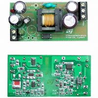
LOW POWER OFF LINE SMPS PRIMARY SWITCHER TYPICAL POWER CAPABILITY Mains type SO-8 European 8 W (195 - 265 Vac Wide range 5 W (85 - 265 Vac) n FIXED 60 KHZ SWITCHING FREQUENCY ...
Page 2
VIPer12ADIP / VIPer12AS PIN FUNCTION Name Power supply of the control circuits. Also provides a charging current during start up thanks to a high voltage current source connected to the drain. For this purpose, an hysteresis comparator monitors the V ...
Page 3
ABSOLUTE MAXIMUM RATINGS Symbol V Switching Drain Source Voltage (T DS(sw) V Start Up Drain Source Voltage (T DS(st) I Continuous Drain Current D V Supply Voltage DD I Feedback Current FB Electrostatic Discharge: V Machine Model (R=0 ; C=200pF) ...
Page 4
VIPer12ADIP / VIPer12AS ELECTRICAL CHARACTERISTICS (T SUPPLY SECTION Symbol Parameter Start Up Charging I DDch Current Start Up Charging I Current DDoff in Thermal Shutdown Operating Supply Current I DD0 Not Switching Operating Supply Current I DD1 Switching D Restart ...
Page 5
Figure 1 : Rise and Fall Time 90 10% Figure 2 : Start Up VDD Current DD0 V DDhyst V V DDoff DDon I DDch Figure 3 ...
Page 6
VIPer12ADIP / VIPer12AS Figure 4 : Peak Drain Current Vs. Feedback Current Dpeak 1/F OSC I FBsd The drain current limitation is obtained for VFB = 0 V, and a negative current is drawn from the FB ...
Page 7
Figure 6 : Switching Frequency vs Temperature 1.01 1 0.99 0.98 0.97 -20 Figure 7 : Current Limitation vs Temperature 1.04 1.03 1.02 1.01 1 0.99 0.98 0.97 0.96 0.95 0.94 -20 Vdd = 10V ... 35V ...
Page 8
VIPer12ADIP / VIPer12AS Figure 8 : Rectangular U-I output characteristics for battery charger RECTANGULAR U-I OUTPUT CHARACTERISTIC A complete regulation scheme can achieve combined and accurate output characteristics. Figure 8 presents a secondary feedback ...
Page 9
FEEDBACK PIN PRINCIPLE OF OPERATION A feedback pin controls the operation of the device. Unlike conventional PWM control circuits which use a voltage input (the inverted input of an operational amplifier), the FB pin is sensitive to current. Figure 9 ...
Page 10
VIPer12ADIP / VIPer12AS Figure 11 : Start Up Sequence DDon V DDoff tss OUT the regulation point where the secondary loop begins to send a current in the optocoupler. At this point, the converter ...
Page 11
SO-8 MECHANICAL DATA mm. DIM. MIN. TYP 0.65 b 0.35 b1 0. 4.8 5 1.27 e3 3.81 F 3 0.8 VIPer12ADIP / VIPer12AS inch ...
Page 12
VIPer12ADIP / VIPer12AS Plastic DIP-8 MECHANICAL DATA DIM Package Weight 12/15 mm. MIN. TYP 0.38 2.92 3.30 0.36 0.46 1.14 1.52 0.20 0.25 9.02 9.27 7.62 7.87 ...
Page 13
SO-8 TUBE SHIPMENT (no suffix) B TAPE AND REEL SHIPMENT (suffix “13TR”) TAPE DIMENSIONS According to Electronic Industries Association (EIA) Standard 481 rev. A, Feb 1986 Tape width W Tape Hole Spacing P0 (± 0.1) Component Spacing P Hole Diameter ...
Page 14
VIPer12ADIP / VIPer12AS A 14/15 DIP-8 TUBE SHIPMENT (no suffix) C Base Q.ty Bulk Q.ty Tube length (± 0. (± 0.1) All dimensions are in mm. 20 1000 532 8.4 11.2 0 ...
Page 15
... STMicroelectronics. Specifications mentioned in this publication are subject to change without notice. This publication supersedes and replaces all information previously supplied. STMicroelectronics products are not authorized for use as critical components in life support devices or systems without express written approval of STMicroelectronics. 2002 STMicroelectronics - Printed in ITALY- All Rights Reserved. ...