STEVAL-ILL008V1 STMicroelectronics, STEVAL-ILL008V1 Datasheet
STEVAL-ILL008V1
Specifications of STEVAL-ILL008V1


Related parts for STEVAL-ILL008V1


STEVAL-ILL008V1 Summary of contents
Page 1
... LED itself. STMicroelectronics has developed the following non-isolated DC-DC con- stant current LED driver to aid designers in developing a low cost and efficient platform for driv- ing high brightness LEDs ...
Page 2
AN1941 APPLICATION NOTE 2 L6920D LED DRIVER White LEDs are gaining popularity as sources of illumination because of their high efficiency and reliability. Typical forward voltage drop of a white LED is approximately 3.5V. When these LEDs are powered from ...
Page 3
Circuit Description The circuit shown in figure constant current control to provide constant luminosity from the LED. A current sensing resistor is in series with the white LED is used to provide the current feedback. The ...
Page 4
AN1941 APPLICATION NOTE Figure 4. Upper trace: inductor current; lower track: LED current Figure 5. Upper trace: inductor current; lower track: LED current from the waveforms, the inductor peak current is limited at 1A. the maximum load current is defined ...
Page 5
Figure 7. Vin = 0.6V; upper trace: inductor current; lower trace: LED current Fig. 8 shows the efficiency of the driver at different load and input voltages. Figure 8. Efficiency curve 1 0.9 0.8 0.7 0.6 0.5 Table 1. Bill ...
Page 6
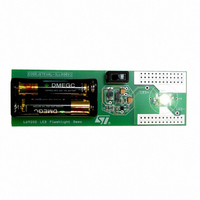
AN1941 APPLICATION NOTE Figure 9. Size of the demo board 3 L4971 BUCK LED DRIVER: For applications that use multiple LEDs it is better to drive LEDs in series rather than parallel. 3.1 LED parameters; As shown below, the LED ...
Page 7
The brightness is directly proportional to the current driving the LED. A test was conducted in a closed box with a white LED mounted 12 inches away from the light meter. The results showed a linear relationship between current and ...
Page 8
AN1941 APPLICATION NOTE Figure 11. 3.3 Circuit description: The input ranges from 20 volts to 55 volts. The switching frequency is set by where R and C represent R2 and C2. osc osc The minimum voltage for the L4971 is ...
Page 9
R3 and R4 set the maximum voltage to 30 volts. R8 will adjust the constant current output from 220 mA to 400 mA. I Table 4. Part List tem Qty ...
Page 10
AN1941 APPLICATION NOTE Figure 12. Current regulation: The current regulation is ± 1% for the range LEDs or a voltage range of 3.3 volts to 29 volts output. Figure 13. Efficiency at 55V input: The efficiency ...
Page 11
L6902D BUCK LED DRIVER: Another buck topology reference design that is much simpler, less expensive and requires fewer external components is the L6902D LED driver. The features of the L6902D are: 4.1 L6902D Description – ...
Page 12
AN1941 APPLICATION NOTE Figure 16. Schematic Vin=8 to 25V 1 C1 10uF 25V C3 220pF GND in 1 4.2 Circuit description: The IC can operate volts. The 25 volt input capacitor was the restricting factor for the ...
Page 13
Results: With a minimum of 8 volts, 1LED can be driven and with the maximum of 25 volts LEDs can be driven. Figure 17. Current regulation The current regulation from LEDs or 3.3V ...
Page 14
AN1941 APPLICATION NOTE 5 CONCLUSION: This application note has shown three reference designs to drive LEDs in constant current mode. One is a boost, to drive a flashlight at a higher voltage than the input. The others are two buck ...
Page 15
... The present note which is for guidance only, aims at providing customers with information regarding their products in order for them to save time result, STMicroelectronics shall not be held liable for any direct, indirect or consequential damages with respect to any claims arising from the content of such a note and/or the use made by customers of the information contained herein in connection with their products ...