STEVAL-ILL008V1 STMicroelectronics, STEVAL-ILL008V1 Datasheet - Page 8
STEVAL-ILL008V1
Manufacturer Part Number
STEVAL-ILL008V1
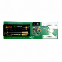
Description
EVAL BOARD CREE LED FLASHLIGHT
Manufacturer
STMicroelectronics
Datasheets
1.L6920DC.pdf
(13 pages)
2.STEVAL-ILL008V1.pdf
(4 pages)
3.STEVAL-ILL008V1.pdf
(15 pages)
Specifications of STEVAL-ILL008V1
Mfg Application Notes
Low Voltage LED Driver AppNote
Design Resources
STEVAL-ILL008V1 Gerber Files STEVAL-ILL008V1 Schematic STEVAL-ILL008V1 Bill of Materials
Outputs And Type
1, Non-Isolated
Voltage - Output
3.5V
Features
1V Start up Input Voltage
Voltage - Input
1 ~ 5.5 V
Utilized Ic / Part
L6920
Product
Display Modules
Core Chip
L6920DA
Output Voltage
3.5V
Kit Contents
L6920D, L4971, L6902D Reference Board
Development Tool Type
Hardware - Eval/Demo Board
Tool / Board Applications
LED Flashlight
Mcu Supported Families
L6920DA
Lead Free Status / RoHS Status
Lead free / RoHS Compliant
Current - Output / Channel
-
Lead Free Status / Rohs Status
Details
Other names
497-5516


AN1941 APPLICATION NOTE
Figure 11.
3.3
The input ranges from 20 volts to 55 volts. The switching frequency is set by
where R
The minimum voltage for the L4971 is 8 volts but the regulator-reference U3 needs a minimum
of 20 volts to stay in regulation. A higher breakdown voltage regulator can be used to achieve
a wider range of input. U3 provides power to the LM393 and a reference for the comparator
input. This voltage is compared to the voltage drop across Rs to maintain it at the same voltage
set by the potentiometer R8. The voltage drop across the resistor is proportional to the current
following through it by:
The output of the LM393 turns on and off to adjust the voltage at the slow start pin. The slow
start voltage is directly related to the output regulation thus achieving a constant current out-
put. The L4971 regulates by adjusting the duty cycle to maintain a constant output. R9 sets
the gain of the loop by controlling the discharge rate. L1 and C8 form the output filter to smooth
out the current. The inductor required is calculated at the worse case which is max input line
and minimum LEDS. This gives the minimum duty cycle and maximum time that the inductor
has to supply current to the load.
8/15
I
o
is the current ripple set by the application, usually 10% of the max current.
Circuit description:
osc
and C
D
max
osc
=
represent R2 and C2.
-----------------------------
V
in min
V
o
+
V
+
F
f
V
SW
f
=
D
Iout = V(U2Apin3)/Rs.
min
------------------------------------------------------------------------------ -
R
osc
=
-----------------------------
V
C
in min
osc
V
o
+
ln
V
+
1
6
-- -
5
f
V
f
+
100 C
L
o
=
os c
V
o
+
V
f
-------------------------- -
1 D
I
–
o
f
min
sw
Related parts for STEVAL-ILL008V1
Image
Part Number
Description
Manufacturer
Datasheet
Request
R

Part Number:
Description:
BOARD EVAL FOR MEMS SENSORS
Manufacturer:
STMicroelectronics
Datasheet:

Part Number:
Description:
KIT DEV STARTER ST10F276Z5
Manufacturer:
STMicroelectronics
Datasheet:

Part Number:
Description:
BOARD EVAL HDMI $ VIDEO SWITCH
Manufacturer:
STMicroelectronics
Datasheet:

Part Number:
Description:
BOARD DEMO ACCELEROMETER DIL24
Manufacturer:
STMicroelectronics
Datasheet:

Part Number:
Description:
BOARD STLM75/STDS75/ST72F651
Manufacturer:
STMicroelectronics
Datasheet:

Part Number:
Description:
EVAL BOARD 3AXIS MEMS ACCELLRMTR
Manufacturer:
STMicroelectronics
Datasheet:

Part Number:
Description:
BOARD EVAL 8BIT MICRO + TDE1708
Manufacturer:
STMicroelectronics
Datasheet:

Part Number:
Description:
EVAL BOARD A/D TS4657
Manufacturer:
STMicroelectronics
Datasheet:

Part Number:
Description:
BOARD ADAPTER 20DIP LIS3LV02DL
Manufacturer:
STMicroelectronics
Datasheet:

Part Number:
Description:
BOARD DEMO STM8S207R6/LIS331DLH
Manufacturer:
STMicroelectronics
Datasheet:

Part Number:
Description:
STMicroelectronics [RIPPLE-CARRY BINARY COUNTER/DIVIDERS]
Manufacturer:
STMicroelectronics
Datasheet:
Part Number:
Description:
STMicroelectronics [LIQUID-CRYSTAL DISPLAY DRIVERS]
Manufacturer:
STMicroelectronics
Datasheet:
Part Number:
Description:
BOARD EVAL FOR MEMS SENSORS
Manufacturer:
STMicroelectronics
Datasheet: