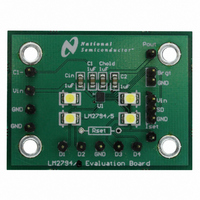
LM2794EVAL National Semiconductor, LM2794EVAL Datasheet - Page 13

LM2794EVAL
Manufacturer Part Number
LM2794EVAL
Description
BOARD EVALUATION LM2794
Manufacturer
National Semiconductor
Specifications of LM2794EVAL
Current - Output / Channel
80mA
Outputs And Type
4, Non-Isolated
Voltage - Output
4 V
Features
Charge Pump
Voltage - Input
2.7 ~ 5.5V
Utilized Ic / Part
LM2794
Lead Free Status / RoHS Status
Not applicable / Not applicable
Application Information
OUTPUT CURRENT CAPABILITY
The primary constraint on the total current capability is the
headroom voltage requirement of the internal current
sources. Combining the V
previous two sections yields the basic inequality for deter-
mining the validity of an LM2794/5 LED-drive application:
Rearranging this inequality shows the estimated total output
current capability of an application:
Examining the equation above, the primary limiting factors
on total output current capability are input and LED forward
voltage. A low input voltage combined with a high LED
voltage may result in insufficient headroom voltage across
the current sources, causing them to fall out of regulation.
When the current sources are not regulated, LED currents
will be below desired levels and brightness matching will be
highly dependent on LED forward voltage matching.
Typical LM2794/5 output resistance is 3.0Ω. For worst-case
design calculations, using an output resistance of 3.5Ω is
recommended. LM2794/5 has a typical k
20mV/mA. For worst-case design calculations, use k
25mV/mA. (Worst-case recommendations account for pa-
rameter shifts from part-to-part variation and apply over the
full operating temperature range). R
slightly with temperature, but losses are typically offset by
the negative temperature coefficient properties of LED for-
ward voltages. Power dissipation and internal self-heating
may also limit output current capability but is discussed in a
later section.
PARALLEL Dx OUTPUTS FOR INCREASED CURRENT
DRIVE
Outputs D
combination to drive higher currents through fewer LEDs.
For example in Figure 4, outputs D
together to drive one LED while D
together to drive a second LED.
I
TOTAL
1.5 x V
≤ [(1.5 x V
FIGURE 4. Two Parallel Connected LEDs
1
V
through D
POUT
IN
− I
V
IN-MIN
TOTAL
= 1.5 x V
POUT
V
HR-MIN
4
) − V
may be connected together in any
− V
x R
POUT
= k
IN
DX
OUT
DX-MAX
− I
and V
HR
≥ V
− V
TOTAL
x I
3
HR-MIN
1
DX
− (k
OUT
and D
DX
and D
HR
x R
≥ (k
HR
equations from the
and k
(Continued)
4
2
OUT
HR
x I
HR
are connected
are connected
DX
x I
HR
constant of
)] ÷ R
DX
increase
)
20028533
HR
OUT
=
13
With this configuration, two parallel current sources of equal
value provide current to each LED. R
therefore be chosen so that the current through each output
is programmed to 50% of the desired current through the
parallel connected LEDs. For example, if 30mA is the de-
sired drive current for 2 parallel connected LEDs , R
V
the outputs is 15mA. Other combinations of parallel outputs
may be implemented in similar fashions, such as in Figure 5.
Connecting outputs in parallel does not affect internal opera-
tion of the LM2794/95 and has no impact on the Electrical
Characteristics and limits previously presented. The avail-
able diode output current, maximum diode voltage, and all
other specifications provided in the Electrical Characteristics
table apply to parallel output configurations, just as they do
to the standard 4-LED application circuit.
THERMAL PROTECTION
When the junction temperature exceeds 150˚C (typ.), the
LM2794/5 internal thermal protection circuitry disables the
part. This feature protects the device from damage due to
excessive power dissipation. The device will recover and
operate normally when the junction temperature falls below
140˚C (typ.). It is important to have good thermal conduction
with a proper layout to reduce thermal resistance.
POWER EFFICIENCY
Figure 6 shows the efficiency of the LM2794/5. The change
in efficiency shown by the graph comes from the transition
from Pass Mode to a gain of 1.5.
Efficiency (E) of the LM2794/5 is defined here as the ratio of
the power consumed by LEDs (P
from the input source (P
quiescent current of the LM2794/5, I
through one LED, V
current, and N is the number of LEDs connected to the
regulated current outputs. In the input power calculation, the
1.5 represents the switched capacitor gain configuration of
the LM2794/5.
BRGT
should be selected so that the current through each of
FIGURE 5. One Parallel Connected LED
P
IN
= V
P
LED
LED
IN
P
= N x V
x (1.5 x N x I
IN
IN
is the forward voltage at that LED
). In the equations below, I
= V
IN
LED
x I
LED
IN
LED
x I
LED
SET
) to the power drawn
LED
is the current flowing
+ I
and V
Q
)
BRGT
www.national.com
SET
Q
should
is the
20028534
and


