LM2794EVAL National Semiconductor, LM2794EVAL Datasheet - Page 14
LM2794EVAL
Manufacturer Part Number
LM2794EVAL
Description
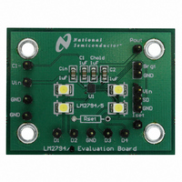
BOARD EVALUATION LM2794
Manufacturer
National Semiconductor
Specifications of LM2794EVAL
Current - Output / Channel
80mA
Outputs And Type
4, Non-Isolated
Voltage - Output
4 V
Features
Charge Pump
Voltage - Input
2.7 ~ 5.5V
Utilized Ic / Part
LM2794
Lead Free Status / RoHS Status
Not applicable / Not applicable


www.national.com
Application Information
Efficiency, as defined here, is in part dependent on LED
voltage. Variation in LED voltage does not affect power
consumed by the circuit and typically does not relate to the
brightness of the LED. For an advanced analysis, it is rec-
ommended that power consumed by the circuit (V
evaluated rather than power efficiency. Figure 7 shows the
power consumption of the LM2794/5 Typical Application Cir-
cuit.
4 LEDs, 2.5 ≤ V
4 LEDs, V
FIGURE 6. Efficiency vs V
FIGURE 7. P
E = (P
LED
DX
= 3.6V, I
LED
≤ 3.9V, I
IN
÷ P
vs V
LED
IN
)
DX
IN
= 15mA
= 15mA
(Continued)
IN
20028537
20028538
IN
x I
IN
) be
14
POWER DISSIPATION
The power dissipation (P
ture (T
is the power generated by the 1.5x charge pump, P
power consumed by the LEDs, P
through the P
is the junction-to-ambient thermal resistance for the micro
SMD-14 package. V
V
current, and I
The junction temperature rating takes precedence over the
ambient temperature rating. The LM2794/5 may be operated
outside the ambient temperature rating, so long as the junc-
tion temperature of the device does not exceed the maxi-
mum operating rating of 100˚C. The maximum ambient tem-
perature rating must be derated in applications where high
power dissipation and/or poor thermal resistance causes the
junction temperature to exceed 100˚C.
MICRO SMD MOUNTING
The LM2794/5 is a 14-bump micro SMD with a bump size of
300 micron diameter. The micro SMD package requires
specific mounting techniques detailed in National Semicon-
ductor Application Note (AN -1112). NSMD (non-solder mask
defined) layout pattern is recommended over the SMD (sol-
der mask defined) since the NSMD requires larger solder
mask openings over the pad size as opposed to the SMD.
This reduces stress on the PCB and prevents possible
cracking at the solder joint. For best results during assembly,
alignment ordinals on the PC board should be used to
facilitate placement of the micro SMD device. Micro SMD is
a wafer level chip size package, which means the dimen-
sions of the package are equal to the die size. As such, the
micro SMD package lacks the plastic encapsulation charac-
teristics of the larger devices and is sensitive to direct expo-
sure to light sources such as infrared, halogen, and sun light.
The wavelengths of these light sources may cause unpre-
dictable operation.
= [1.5xV
DX
is the LED forward voltage, I
J
) can be approximated with the equations below. P
IN
x(4I
P
OUT
POUT
DISSIPATION
DX
T
J
pin, T
= T
+ I
is the current drawn through P
IN
POUT
A
is the input voltage to the LM2794/5,
A
+ (P
is the ambient temperature, and θ
DISSIPATION
)] − (V
= P
DISSIPATION
IN
- P
DX
POUT
DX
x4I
LED
is the programmed LED
) and junction tempera-
DX
is the power provided
− P
x θ
) − (1.5xV
JA
POUT
)
OUT
IN
LED
xI
POUT
.
is the
JA
IN
)
Related parts for LM2794EVAL
Image
Part Number
Description
Manufacturer
Datasheet
Request
R

Part Number:
Description:
Accurate, 120 C-150 C Factory Preset Thermostat Lm27 Form
Manufacturer:
National Semiconductor Corporation
Datasheet:

Part Number:
Description:
Factory Preset Thermostat
Manufacturer:
National Semiconductor
Datasheet:
Part Number:
Description:
National Semiconductor [8-Bit D/A Converter]
Manufacturer:
National Semiconductor
Datasheet:
Part Number:
Description:
National Semiconductor [Media Coprocessor]
Manufacturer:
National Semiconductor
Datasheet:
Part Number:
Description:
Digitally Controlled Tone and Volume Circuit with Stereo Audio Power Amplifier, Microphone Preamp Stage and National 3D Sound
Manufacturer:
National Semiconductor
Datasheet:
Part Number:
Description:
Digitally Controlled Tone and Volume Circuit with Stereo Audio Power Amplifier, Microphone Preamp Stage and National 3D Sound
Manufacturer:
National Semiconductor
Datasheet:
Part Number:
Description:
AC97 Rev 2 Codec with Sample Rate Conversion and National 3D Sound
Manufacturer:
National Semiconductor
Part Number:
Description:
Manufacturer:
National Semiconductor
Datasheet:
Part Number:
Description:
Manufacturer:
National Semiconductor
Datasheet:
Part Number:
Description:
General Purpose, Low Voltage, Low Power, Rail-to-Rail Output Operational Amplifiers
Manufacturer:
National Semiconductor
Datasheet:
Part Number:
Description:
8-bit 20 MSPS flash A/D converter.
Manufacturer:
National Semiconductor
Datasheet:
Part Number:
Description:
Low Noise Quad Operational Amplifier
Manufacturer:
National Semiconductor
Datasheet:
Part Number:
Description:
Quad Differential Line Receivers
Manufacturer:
National Semiconductor
Datasheet:
Part Number:
Description:
Quad High Speed Trapezoidal? Bus Transceiver
Manufacturer:
National Semiconductor
Datasheet: