AS5040 DB V2 austriamicrosystems, AS5040 DB V2 Datasheet - Page 18
AS5040 DB V2
Manufacturer Part Number
AS5040 DB V2
Description
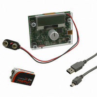
BOARD DEMO AS5040
Manufacturer
austriamicrosystems
Specifications of AS5040 DB V2
Sensor Type
Magnetic, Rotary Position
Sensing Range
360°
Interface
USB
Voltage - Supply
5V USB or 9V
Embedded
Yes, MCU, 8-Bit
Utilized Ic / Part
AS5040
Lead Free Status / RoHS Status
Lead free by exemption / RoHS compliant by exemption
Sensitivity
-


AS5040
Data Sheet
Figure 16: OTP Programming Connection of AS5040 (shown with AS5040 demoboard)
Incremental Mode Programming
Three different incremental output modes are available.
In both modes, the incremental resolution may be reduced from 10 bit down to 9, 8 or 7 bit using the divider OTP bits
Div1 and Div0. (see Table 6 below ).
To allow programming of all bits, the default factory setting is all bits = 0. This mode is equal to mode 1:0 (quadrature
A/B, 1LSB index width, 256ppr).
The absolute angular output value, by default, increases with clockwise rotation of the magnet (top view).
Setting the CCW-bit (see Figure 14) allows reversing the indicated direction, e.g. when the magnet is placed
underneath the IC:
By default, the zero / index position pulse is one LSB wide. It can be increased to a three LSB wide pulse by setting
the Index-bit of the OTP register.
Further programming options (commutation modes) are available for brushless DC motor-control.
Md1 = Md0 = 1 changes the incremental output pins 3, 4 and 6 to a 3-phase commutation signal. Div1 defines the
number of pulses per revolution for either a two-pole (Div1=0) or four-pole (Div1=1) rotor.
In addition, the LSB is available at pin 12 (the LSB signal replaces the PWM signal), which allows for high rotational
speed measurement of up to 30,000 rpm.
www.austriamicrosystems.com
Mode: Md1=0 / Md0=1 sets the AS5040 in quadrature mode.
Mode: Md1=1 / Md0=0 sets the AS5040 in step / direction mode (see Table 1)
Mode: Md1=1 / Md0=1 sets the AS5040 in brushless DC motor commutation mode with an additional LSB
incremental signal at pin 12 (PWM_LSB).
CCW = 0 – angular value increases clockwise;
CCW = 1 – angular value increases counterclockwise.
Revision 2.10
18 - 33
Related parts for AS5040 DB V2
Image
Part Number
Description
Manufacturer
Datasheet
Request
R

Part Number:
Description:
IC ENCODER PROG 10-BIT 16-SSOP
Manufacturer:
austriamicrosystems
Datasheet:

Part Number:
Description:
BOARD ADAPTER AS5040
Manufacturer:
austriamicrosystems
Datasheet:

Part Number:
Description:
BOARD PROGRAM AS5040
Manufacturer:
austriamicrosystems
Datasheet:
Part Number:
Description:
IC ENCODER PROG 10-BIT 16-SSOP
Manufacturer:
austriamicrosystems
Datasheet:
Part Number:
Description:
10-bit Programmable Magnetic Rotary Encoder
Manufacturer:
austriamicrosystems
Datasheet:
Part Number:
Description:
IC SWITCH QUAD SPST 14-TSSOP
Manufacturer:
austriamicrosystems
Datasheet:
Part Number:
Description:
IC SWITCH QUAD SPST 14-TSSOP
Manufacturer:
austriamicrosystems
Datasheet:
Part Number:
Description:
IC AMP AUDIO MONO 1.8W 10-MSOP
Manufacturer:
austriamicrosystems
Datasheet:
Part Number:
Description:
IC AMP AUDIO MONO 1.8W 10-MSOP
Manufacturer:
austriamicrosystems
Datasheet:
Part Number:
Description:
IC AMP AUDIO MONO 1.8W 10-MSOP
Manufacturer:
austriamicrosystems
Datasheet:
Part Number:
Description:
IC AMP AUD 1.8W 3DB GAIN 10-MSOP
Manufacturer:
austriamicrosystems
Datasheet:
Part Number:
Description:
IC DRIVER LED 8-DIGIT 24-SOIC
Manufacturer:
austriamicrosystems
Datasheet:
Part Number:
Description:
IC DRIVER LED 8-DIGIT 24-SOIC
Manufacturer:
austriamicrosystems
Datasheet:
Part Number:
Description:
IC, LINE/SPEAKER PHONE CIRCUIT, SOIC-28
Manufacturer:
austriamicrosystems
Datasheet:
Part Number:
Description:
IC MULTI-STANDARD CMOS TELEPHONE SOIC-28
Manufacturer:
austriamicrosystems
Datasheet: