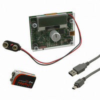
AS5040 DB V2 austriamicrosystems, AS5040 DB V2 Datasheet - Page 23

AS5040 DB V2
Manufacturer Part Number
AS5040 DB V2
Description
BOARD DEMO AS5040
Manufacturer
austriamicrosystems
Specifications of AS5040 DB V2
Sensor Type
Magnetic, Rotary Position
Sensing Range
360°
Interface
USB
Voltage - Supply
5V USB or 9V
Embedded
Yes, MCU, 8-Bit
Utilized Ic / Part
AS5040
Lead Free Status / RoHS Status
Lead free by exemption / RoHS compliant by exemption
Sensitivity
-
AS5040
Data Sheet
Figure 20: Typical Magnet and Magnetic Field Distribution
Physical Placement of the Magnet
The best linearity can be achieved by placing the center of the magnet exactly over the defined center of the IC
package as shown in Figure 21:
Figure 21: Defined IC Center and Magnet Displacement Radius
Magnet Placement
The magnet’s center axis should be aligned within a displacement radius R
IC with reference to the edge of pin #1 (see Figure 21). This radius includes the placement tolerance of the chip within
the SSOP-16 package (+/- 0.235mm). The displacement radius R
(see section 13: Alignment Mode)
www.austriamicrosystems.com
Vertical field
component
N
2.433 mm
2.433 mm
R1
typ. 6mm diameter
R1 concentric circle;
radius 1.1mm
S
Magnet axis
Magnet axis
N
1
S
Area of recommended maximum
magnet misalignment
3.9 mm
Revision 2.10
R
d
d
is 0.485mm with reference to the center of the chip
Vertical field
component
Defined
center
3.9 mm
Bv
d
of 0.25mm from the defined center of the
0
(45…75mT)
360
23 - 33


