P0305 Terasic Technologies Inc, P0305 Datasheet - Page 12
P0305
Manufacturer Part Number
P0305
Description
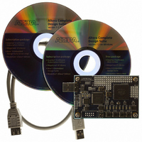
KIT MAX II MICRO
Manufacturer
Terasic Technologies Inc
Series
MAX® IIr
Type
FPGAr
Datasheet
1.P0305.pdf
(26 pages)
Specifications of P0305
Contents
Evaluation Board, Cable(s), Software and Documentation
For Use With/related Products
EPM2210F324
Lead Free Status / RoHS Status
Lead free / RoHS Compliant


2.4
The MAX II Micro board comes with a pre-loaded configuration bit stream to demonstrate various
LED modes. This bit stream also allows users to see quickly if the board is working properly. For
communication between the host and the MAX II Micro board, it is necessary to install the Altera
USB Blaster driver software. The driver only supports Windows OS, and if it is not already installed
on the host computer, it can be installed as explained in the Altera website :
For XP:
For 2000:
At this point you should observe LEDs turn ON/OFF in sequence There are 2 different modes
pre-loaded and it can be changed by pressing Button1. Each mode can be reset by pressing
corresponding Button3 and Button4.
P ower-up the MAX II Micro Board
8 B
h ttp://www.altera.com/support/software/drivers/usb-blaster/dri-usb-blaster-2000.html
H U
h ttp://www.altera.com/support/software/drivers/usb-blaster/dri-usb-blaster-xp.html
H U
GND GND GND GND GND GND
H3
H4
J3
5V
Figure 2.7. The detailed I/O map of prototyping area A and B.
G4
G3
F3
3.3 3.3V 3.3V 3.3V 3.3V
F4
C3
E3
E4
D3
B3
D4
C4
A2
GND
3.3V
C2
C9 C10 D10 C11 D11 C12 D12 C13
B5
D1
G1
F2
J2
J1
Prototyping Area A
B6
B4
D2
E1
G2
H1
(PROTO_A)
A6
E2
A4
B1
H2
F1
A7
A5
10
A8
B7
A9 B10 A11
B8
B9
A10 B11 B12 B13 B14 B15 B18
GND
5V
Prototyping Area B
D13 C14 D14 C15 B16
A12 A13 A14 A15 A17
(PROTO_B)
D17 D18
H18 J17 J18 CLK2
K18 K17 L18 L17
M18 M17
E17 E18 F18 F17
G17 G18 H17 CLK3
GND
GND
3.3V
3.3V
MMK User Manual
U H
.
U
Related parts for P0305
Image
Part Number
Description
Manufacturer
Datasheet
Request
R

Part Number:
Description:
MODULE DIGITAL CAMERA 5MP (D5M)
Manufacturer:
Terasic Technologies Inc
Datasheet:

Part Number:
Description:
DE2-70 CALL FOR ACADEMIC PRICING
Manufacturer:
Terasic Technologies Inc
Datasheet:

Part Number:
Description:
USB BLASTER CABLE
Manufacturer:
Terasic Technologies Inc
Datasheet:

Part Number:
Description:
BOARD ADAPTER HSMC TO GPIO
Manufacturer:
Terasic Technologies Inc
Datasheet:

Part Number:
Description:
BOARD ADAPTER THDB-SUM
Manufacturer:
Terasic Technologies Inc
Datasheet:

Part Number:
Description:
KIT DEV 4.3" LCD TOUCH PANEL
Manufacturer:
Terasic Technologies Inc
Datasheet:

Part Number:
Description:
DAUGHTER BOARD AD/DA GPIO ADA
Manufacturer:
Terasic Technologies Inc

Part Number:
Description:
DAUGHTER BOARD AD/DA HSMC ADA
Manufacturer:
Terasic Technologies Inc

Part Number:
Description:
BOARD DEV/EDUCATION ALTERA DE0
Manufacturer:
Terasic Technologies Inc
Datasheet:

Part Number:
Description:
BOARD DEV DE1 ALTERA
Manufacturer:
Terasic Technologies Inc
Datasheet:

Part Number:
Description:
DE2 CALL FOR ACADEMIC PRICING
Manufacturer:
Terasic Technologies Inc

Part Number:
Description:
MODULE DIGITAL CAMERA 1.3MP
Manufacturer:
Terasic Technologies Inc
Datasheet:

Part Number:
Description:
SENSOR CMOS 1.3MEGA (FOR P0349)
Manufacturer:
Terasic Technologies Inc
Datasheet:
Part Number:
Description:
MODULE DIGITAL CAMERA 5MP (D5M)
Manufacturer:
Terasic Technologies Inc
Datasheet: