C8051F120DK Silicon Laboratories Inc, C8051F120DK Datasheet - Page 213
C8051F120DK
Manufacturer Part Number
C8051F120DK
Description
DEVKIT-F120/21/22/23/24/25/26/27
Manufacturer
Silicon Laboratories Inc
Type
MCUr
Datasheet
1.C8051F120DK.pdf
(350 pages)
Specifications of C8051F120DK
Contents
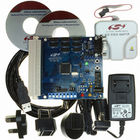
Evaluation Board, Power Supply, USB Cables, Adapter and Documentation
Processor To Be Evaluated
C8051F12x and C8051F13x
Interface Type
USB
Silicon Manufacturer
Silicon Labs
Core Architecture
8051
Silicon Core Number
C8051F120
Silicon Family Name
C8051F12x
Lead Free Status / RoHS Status
Contains lead / RoHS non-compliant
For Use With/related Products
C8051F120, 121, 122, 123, 124, 125, 126, 127
Lead Free Status / Rohs Status
Lead free / RoHS Compliant
Other names
336-1224
Available stocks
Company
Part Number
Manufacturer
Quantity
Price
Company:

Part Number:
C8051F120DK
Manufacturer:
SiliconL
Quantity:
4


C8051F120/1/2/3/4/5/6/7
C8051F130/1/2/3
Certain types of instruction data or certain blocks of code can also be excluded from caching. The destina-
tions of RETI instructions are, by default, excluded from caching. To enable caching of RETI destinations,
the CHRETI bit (CCH0CN.3) can be set to ‘1’. It is generally not beneficial to cache RETI destinations
unless the same instruction is likely to be interrupted repeatedly (such as a code loop that is waiting for an
interrupt to happen). Instructions that are part of an interrupt service routine (ISR) can also be excluded
from caching. By default, ISR instructions are cached, but this can be disabled by clearing the CHISR bit
(CCH0CN.2) to ‘0’. The other information that can be explicitly excluded from caching are the data
returned by MOVC instructions. Clearing the CHMOV bit (CCH0CN.1) to ‘0’ will disable caching of MOVC
data. If MOVC caching is allowed, it can be restricted to only use slot 0 for the MOVC information (exclud-
ing cache push operations). The CHFIXM bit (CCH0TN.2) controls this behavior.
Further cache control can be implemented by disabling all cache writes. Cache writes can be disabled by
clearing the CHWREN bit (CCH0CN.7) to ‘0’. Although normal cache writes (such as those after a cache
miss) are disabled, data can still be written to the cache with a cache push operation. Disabling cache
writes can be used to prevent a non-critical section of code from changing the cache contents. Note that
regardless of the value of CHWREN, a Flash write or erase operation automatically removes the affected
bytes from the cache. Cache reads and the prefetch engine can also be individually disabled. Disabling
cache reads forces all instructions data to execute from Flash memory or from the prefetch engine. To dis-
able cache reads, the CHRDEN bit (CCH0CN.6) can be cleared to ‘0’. Note that when cache reads are
disabled, cache writes will still occur (if CHWREN is set to ‘1’). Disabling the prefetch engine is accom-
plished using the CHPFEN bit (CCH0CN.5). When this bit is cleared to ‘0’, the prefetch engine will be dis-
abled. If both CHPFEN and CHRDEN are ‘0’, code will execute at a fixed rate, as instructions become
available from the Flash memory.
Cache locations can also be pre-loaded and locked with time-critical branch destinations. For example, in
a system with an ISR that must respond as fast as possible, the entry point for the ISR can be locked into
a cache location to minimize the response latency of the ISR. Up to 61 locations can be locked into the
cache at one time. Instructions are locked into cache by enabling cache push operations with the
CHPUSH bit (CCH0LC.7). When CHPUSH is set to ‘1’, a MOVC instruction will cause the four-byte seg-
ment containing the data byte to be written to the cache slot location indicated by CHSLOT (CCH0LC.5-0).
CHSLOT is them decremented to point to the next lockable cache location. This process is called a cache
push operation. Cache locations that are above CHSLOT are “locked”, and cannot be changed by the pro-
cessor core, as shown in Figure 16.3. Cache locations can be unlocked by using a cache pop operation.
A cache pop is performed by writing a ‘1’ to the CHPOP bit (CCH0LC.6). When a cache pop is initiated,
the value of CHSLOT is incremented. This unlocks the most recently locked cache location, but does not
remove the information from the cache. Note that a cache pop should not be initiated if CHSLOT is equal
to 111110b. Doing so may have an adverse effect on cache performance. Important: Although locking
cache location 1 is not explicitly disabled by hardware, the entire cache will be unlocked when
CHSLOT is equal to 000000b. Therefore, cache locations 1 and 0 must remain unlocked at all
times.
Rev. 1.4
213
Related parts for C8051F120DK
Image
Part Number
Description
Manufacturer
Datasheet
Request
R

Part Number:
Description:
SMD/C°/SINGLE-ENDED OUTPUT SILICON OSCILLATOR
Manufacturer:
Silicon Laboratories Inc
Part Number:
Description:
Manufacturer:
Silicon Laboratories Inc
Datasheet:
Part Number:
Description:
N/A N/A/SI4010 AES KEYFOB DEMO WITH LCD RX
Manufacturer:
Silicon Laboratories Inc
Datasheet:
Part Number:
Description:
N/A N/A/SI4010 SIMPLIFIED KEY FOB DEMO WITH LED RX
Manufacturer:
Silicon Laboratories Inc
Datasheet:
Part Number:
Description:
N/A/-40 TO 85 OC/EZLINK MODULE; F930/4432 HIGH BAND (REV E/B1)
Manufacturer:
Silicon Laboratories Inc
Part Number:
Description:
EZLink Module; F930/4432 Low Band (rev e/B1)
Manufacturer:
Silicon Laboratories Inc
Part Number:
Description:
I°/4460 10 DBM RADIO TEST CARD 434 MHZ
Manufacturer:
Silicon Laboratories Inc
Part Number:
Description:
I°/4461 14 DBM RADIO TEST CARD 868 MHZ
Manufacturer:
Silicon Laboratories Inc
Part Number:
Description:
I°/4463 20 DBM RFSWITCH RADIO TEST CARD 460 MHZ
Manufacturer:
Silicon Laboratories Inc
Part Number:
Description:
I°/4463 20 DBM RADIO TEST CARD 868 MHZ
Manufacturer:
Silicon Laboratories Inc
Part Number:
Description:
I°/4463 27 DBM RADIO TEST CARD 868 MHZ
Manufacturer:
Silicon Laboratories Inc
Part Number:
Description:
I°/4463 SKYWORKS 30 DBM RADIO TEST CARD 915 MHZ
Manufacturer:
Silicon Laboratories Inc
Part Number:
Description:
N/A N/A/-40 TO 85 OC/4463 RFMD 30 DBM RADIO TEST CARD 915 MHZ
Manufacturer:
Silicon Laboratories Inc
Part Number:
Description:
I°/4463 20 DBM RADIO TEST CARD 169 MHZ
Manufacturer:
Silicon Laboratories Inc