DK-MAXII-1270N Altera, DK-MAXII-1270N Datasheet - Page 15
DK-MAXII-1270N
Manufacturer Part Number
DK-MAXII-1270N
Description
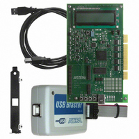
KIT DEV MAXII W/EPM 1270N
Manufacturer
Altera
Series
MAX® IIr
Type
CPLDr
Specifications of DK-MAXII-1270N
Contents
Dev Board, Quartus®II Web Edition, Nios®II Web Edition, Cables, Accessories, Reference Designs and Demos
Silicon Manufacturer
Altera
Core Architecture
CPLD
Core Sub-architecture
MAX
Silicon Core Number
EPM
Silicon Family Name
MAX II
Rohs Compliant
Yes
For Use With/related Products
MAX®II CPLDs
Lead Free Status / RoHS Status
Lead free / RoHS Compliant
Other names
544-2380
Available stocks
Company
Part Number
Manufacturer
Quantity
Price


Demo Designs
Altera Corporation
July 2005
If all tests pass, the MAX II development board is ready to use.
Altera provides several demos and reference designs with the MAX II
Development Kit to help you get started building applications and to
demonstrate the features of the MAX II device. The next two sections
describe the functionality of these designs.
The MAX II Development Kit includes three demos that illustrate
features of the MAX II device:
■
■
■
Power-Up Time Demonstration
MAX II devices power up and configure very quickly and may be used to
perform vital power-up functions. In order to allow users to investigate
the fast power-up time of a MAX II device, the board is equipped with a
circuit that allows users to observe the time it takes for a MAX II device
to power up under a variety of different power supply loading
conditions. This circuit allows users to increase or decrease the load on
the V
rate) of the MAX II V
mimic the load that the MAX II device’s V
on a custom piece of hardware. This knowledge allows you to verify that
the MAX II device will be powered up and configured quickly enough to
perform whatever power up functions are required in the user system.
d.
e.
f.
g.
h.
i.
“Power-Up Time Demonstration”
“Low Power Demonstration”
“Real-Time ISP Demonstration”
CCINT
Development Kit Version 1.1.0
Pressing S2 a fourth time will display the value of I
Pressing S2 a fifth time will display the board temperature,
which should be between 18° C and 23° C, depending on your
room temperature.
Pressing S2 a sixth time will display the LED test—LEDs 1-4
should light up and turn off one at a time.
Pressing S2 a seventh time will display the SRAM test—the
LCD will indicate Pass or Fail.
Pressing S2 for the eighth time will display the LCD test—note
the text: “LCD Does Work!”
Pressing S2 for the ninth time returns to the start up screen. The
LCD display reads: “MAX II by Altera”
voltage plane. As this load is increased, the ramp time (or slew
CCINT
MAX II Development Kit Getting Started User Guide
voltage increases. Using this circuit you can
CCINT
voltage plane will have
Getting Started
IO
.
2–7
Related parts for DK-MAXII-1270N
Image
Part Number
Description
Manufacturer
Datasheet
Request
R

Part Number:
Description:
KIT DEV MAX V 5M570Z
Manufacturer:
Altera
Datasheet:

Part Number:
Description:
CYCLONE II STARTER KIT EP2C20N
Manufacturer:
Altera
Datasheet:


Part Number:
Description:
CPLD, EP610 Family, ECMOS Process, 300 Gates, 16 Macro Cells, 16 Reg., 16 User I/Os, 5V Supply, 35 Speed Grade, 24DIP
Manufacturer:
Altera Corporation
Datasheet:
Part Number:
Description:
CPLD, EP610 Family, ECMOS Process, 300 Gates, 16 Macro Cells, 16 Reg., 16 User I/Os, 5V Supply, 15 Speed Grade, 24DIP
Manufacturer:
Altera Corporation
Datasheet:
Part Number:
Description:
Manufacturer:
Altera Corporation
Datasheet:
Part Number:
Description:
CPLD, EP610 Family, ECMOS Process, 300 Gates, 16 Macro Cells, 16 Reg., 16 User I/Os, 5V Supply, 30 Speed Grade, 24DIP
Manufacturer:
Altera Corporation
Datasheet:
Part Number:
Description:
High-performance, low-power erasable programmable logic devices with 8 macrocells, 10ns
Manufacturer:
Altera Corporation
Datasheet:
Part Number:
Description:
High-performance, low-power erasable programmable logic devices with 8 macrocells, 7ns
Manufacturer:
Altera Corporation
Datasheet:
Part Number:
Description:
Classic EPLD
Manufacturer:
Altera Corporation
Datasheet:
Part Number:
Description:
High-performance, low-power erasable programmable logic devices with 8 macrocells, 10ns
Manufacturer:
Altera Corporation
Datasheet:
Part Number:
Description:
Manufacturer:
Altera Corporation
Datasheet:
Part Number:
Description:
Manufacturer:
Altera Corporation
Datasheet:
Part Number:
Description:
Manufacturer:
Altera Corporation
Datasheet: