ATSTK526 Atmel, ATSTK526 Datasheet
ATSTK526
Specifications of ATSTK526


Related parts for ATSTK526


ATSTK526 Summary of contents
Page 1
STK526 Rev. B .............................................................................................. Hardware User Guide ...
Page 2
STK526 rev. B Hardware User Guide Section 1 Introduction ........................................................................................... 1-2 1.1 Overview ...................................................................................................1-2 1.2 STK526 - AT90USB82/162 Starter Kit Features.......................................1-3 Section 2 Using the STK526................................................................................. 2-5 2.1 Overview ...................................................................................................2-5 2.2 Power Supply ............................................................................................2-6 2.3 RESET ....................................................................................................2-10 2.4 AT90USB82/162 AVR ...
Page 3
... This document applies to the revision B of the board. To complement the evaluation and enable additional development capability, the STK526 can be plugged into the Atmel STK500 Starter Kit Board in order to use the AT90USB82/162 with advanced features such as variable VCC, variable XTAL, Parallel Programming, and supports all AVR development tools ...
Page 4
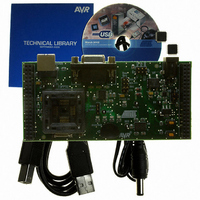
STK526 - AT90USB82/162 Starter Kit Features STK526 rev. B Hardware User Guide Figure 1-1 . STK526 Board The STK526 rev. B provides the following features: AT90USB82/162 TQFP device (2.7V<Vcc<5.5V) AVR Studio® software interface USB software interface for Device Firmware ...
Page 5
... AVR Studio®, AVR tools and this User Guide can be found in the AVR section of the Atmel web site, http://www.atmel.com. 2. ATMEL Flip®, In System Programming Version 3 or Higher shall be used for Device Firmware Upgrade. Please consult Atmel web site to retrieve the latest version of Flip and the DFU bootloader Hex file if needed ...
Page 6
Overview USB STK526 rev. B Hardware User Guide This chapter describes the board and all its features. Figure 2-1 . STK526 Overview RS232 3V3 Reg Joystick Crystal LEDs Section 2 Using the STK526 Power SPI / debugWire Vcc Source ...
Page 7
Using the STK526 2.2 Power Supply 2.2.1 Power Supply Sources USB powered: When used as a USB device bus powered application, the STK526 can be powered via JACK PWR connector: 2-6 7709B–AVR–07/08 The on-board power supply circuitry allows different power ...
Page 8
STK500 Powered: (c.f. STK526 rev. B Hardware User Guide Figure 2-3 . JACK PWR Connector (J6) Figure 2-4 . Male JACK Outlet and Wires + - “STK500 Resources” on page 17 Notes: 1. Caution: Do not set more than one ...
Page 9
Using the STK526 2.2.2 Power Source Setting Vcc Source Jumper position VBUS REG 5V REG 3V3 STK & REG 5V 2-8 7709B–AVR–07/08 (1) Table 2-1 . Power Supply Setting VCC power Comments supply value This is the default configuration. This ...
Page 10
AT90USB82/162 Power Configuration Settings “3V3 REG” AT90USB16 I/O power supply Jumper position “NOREG” Primary power source “INTREG” Internal regulator STK526 rev. B Hardware User Guide This section applies to the following part of the power path diagram : Figure ...
Page 11
Using the STK526 2.2.4 “POWER-ON“ LED 2.3 RESET 2.3.1 Power-on RESET 2.3.2 RESET Push Button 2.3.3 STK500 RESET 2-10 7709B–AVR–07/08 The POWER-ON LED is lit whenever power is applied to STK526 regardless of the power supply source and the voltage ...
Page 12
AT90USB82/162 AVR Microcontroller 2.4.1 Main Clock XTAL 2.4.2 Analog Power Supply AVCC AVCC is tied to VCC by hardware. 2.5 Serial Links 2.5.1 USB STK526 rev. B Hardware User Guide To use the USB interface of the AT90USBxxx, the ...
Page 13
Using the STK526 VBUS Detection The board also implements a VBUS detection on a generic I/O. A low-power (50µA) VBUS Power Source Moreover, even if not selected as primary power source, VBUS powers the on-board 2-12 7709B–AVR–07/08 voltage divider (/2) ...
Page 14
RS-232C STK526 rev. B Hardware User Guide The AT90USB82/162 is a microcontroller with an on-chip USART peripheral (USART1). Only the asynchronous mode is supported by the STK526. The STK526 is supplied with a RS-232 driver/receiver. One female DB9 connector ...
Page 15
Using the STK526 2-14 7709B–AVR–07/08 The STK526 USART implementation allows an optional hardware flow control that can be enabled thanks to SP2, SP3, SP4, SP5 solder pads. Figure 2-13 . USART Schematic C9 100nF C10 PD[7..0] 100nF PD2 RxD PD3 ...
Page 16
On-board Resources 2.6.1 Joystick 2.6.2 LEDs STK526 rev. B Hardware User Guide The 4+1 ways joystick is convenient for developing input device (USB) application: it can easily emulate mouse movements, keyboard inputs, etc. Closing a switch causes the corresponding ...
Page 17
Using the STK526 2.6.3 Data Flash Memory 2-16 7709B–AVR–07/08 Figure 2-18 . LEDs Implementation Schematic In-line Grouped LEDs 1k R1 LED 0 (green) TOPLED LP M676 1k R2 LED 1 (green) TOPLED LP M676 1k R3 LED 2 (green) TOPLED ...
Page 18
STK500 Resources 2.7.1 Supply Voltage from STK500 2.7.2 EXP.CON 0 & EXP.CON 1 Connectors STK526 rev. B Hardware User Guide Figure 2-20 . Connecting STK526 to the STK500 Board Note: Caution: Do not mount an AVR microcontroller on the ...
Page 19
Using the STK526 2.7.3 Main Clock from STK500 2.7.4 RESET from STK500 2.8 In-System Programming 2.8.1 Programming with USB bootloader: DFU (Device Firmware Upgrade) 2-18 7709B–AVR–07/08 Figure 2-21 . EXP.CON 0 and EXP.CON 1 Connectors GND 1 2 GND n.c. ...
Page 20
Programming with AVR ISP mkII Programmer 2.8.3 Programming with AVR JTAG ICE STK526 rev. B Hardware User Guide For more information about the USB bootloader and FLIP software, please refer to the ‘USB bootloader datasheet’ and ‘FLIP User Manual’. ...
Page 21
Using the STK526 2.8.4 Programming with STK500 Serial Programming The AT90USB82/162 can be programmed using the serial programming mode from 2-20 7709B–AVR–07/08 The AT90USB82/162 can be programmed using ISP capability of the JTAGICE (using the connector adapter that comes with ...
Page 22
Parallel High-Voltage Programming STK526 rev. B Hardware User Guide The STK526 is compatible with the Parallel Programming mode of the STK500. The embedded RESET circuitry supports the HighVoltage pulses used during programming. Once the STK526 is plugged into the STK500 ...
Page 23
... JTAG ICE MK II. Thus the on-chip flash bootloader will be erased. It can be restored after the debug session using the bootloader hex file available from ATMEL website or from the CD- ROM included in the starter kit. ...
Page 24
Test Points STK526 rev. B Hardware User Guide There are 7 test points implemented, these test points are referred in the full schematics section. Config. Pads Related Signals Reference TP1 D+ USB D+ data line TP2 D- USB D- ...
Page 25
Using the STK526 2.11 Configuration Pads 2.11.1 Configuration Pads Listing 2.11.2 Configuration Pads - Disconnection 2.11.3 Configuration Pads - Connection 2-24 7709B–AVR–07/08 to Configuration pads are used disconnect/connect on-board peripherals or elements, their default configuration is: connect. Table 2-4 . ...
Page 26
Solder Pads 2.12.1 Solder Pads Listing STK526 rev. B Hardware User Guide Solder pads are used to disconnect/connect on-board peripherals or elements, their default configuration is: disconnect. User may solder the pad to enable it. Table 2-5 . Solder ...
Page 27
STK526 rev. B Hardware User Guide Troubleshooting Guide Figure 3-1 . Troubleshooting Guide Problem Reason The Green “Power-ON” LED is not on No power supply STK526 does not work STK500 Configuration not respected. The AVR ISP probe is not connected ...
Page 28
STK526 rev. B Hardware User Guide Troubleshooting Guide 3-27 7709B–AVR–07/08 ...
Page 29
STK526 rev. B Hardware User Guide Technical Specifications System Unit – Physical Dimensions ................................................. L=119 x W=56 x H=27 mm – Weight ...........................................................................................................70 g Operating Conditions – Internal Voltage Supply .....................................................................2.7V - 5.5V – External Voltage Supply ..........................................................9V -15V (100mA) ...
Page 30
... STK526 rev. B Hardware User Guide For Technical support, please contact avr@atmel.com. When requesting technical support, please include the following information: Which target AVR device is used (complete part number) Target voltage and speed Clock source and fuse setting of the AVR Programming method (ISP, Parallel or specific Boot-Loader) Hardware revisions of the AVR tools, found on the PCB Version number of AVR Studio ...
Page 31
STK526 rev. B Hardware User Guide On the next pages, the following documents of STK526 revision 4381B are shown: Complete schematics Assembly drawing Bill of materials Default configuration summary Section 6 Complete Schematics 6-30 7709B–AVR–07/08 ...
Page 32
UGND UGND UGND UGND UGND UGND STK526 rev. B Hardware User Guide Figure 6-1 . Schematics PC5 PB2 25 16 PC5 PB2 PC4 PB1 26 15 PC4 PB1 UCAP PB0 27 14 UCAP ...
Page 33
Complete Schematics 6-32 7709B–AVR–07/08 Figure 6-2 . Schematics STK526 rev. B Hardware User Guide ...
Page 34
STK526 rev. B Hardware User Guide Figure 6-3 . Schematics Complete Schematics 6-33 7709B–AVR–07/08 ...
Page 35
Complete Schematics 6-34 7709B–AVR–07/08 Figure 6-4 . Schematics STK526 rev. B Hardware User Guide ...
Page 36
STK526 rev. B Hardware User Guide Figure 6-5 . Assembly Drawing (component side) Complete Schematics 6-35 7709B–AVR–07/08 ...
Page 37
Complete Schematics Table 6-1 . Bill of Materials Schematic Qtty Part Reference Reference 14 C1, C2, C3, C6- 100nF C14, C16, C123 1 C121 2.2µF 1 C19 220nF 1 C20 33nF 2 C21, C28 1nF 3 C23, C24, C122 4.7µF ...
Page 38
Table 6-1 . Bill of Materials Schematic Qtty Part Reference Reference 1 U1 socket TQFP32 ZIF 1 U20 AT90USBxx2 1 U9 AT45DB642C 1 U3 MAX3232ECAE LM340 1 U6 LP3982IMM-ADJ 1 U7 DBS104G 1 U8 BC847BPN 2 SW1, SW2 ...
Page 39
Complete Schematics 6.1 Document Revision History 6.2 7709B 6-38 7709B–AVR–07/08 1. Schematic drawings updated. STK526 rev. B Hardware User Guide ...
Page 40
... Disclaimer: The information in this document is provided in connection with Atmel products. No license, express or implied, by estoppel or otherwise,to anyintellectu- alproperty right is granted by this document or in connection with the sale of Atmel products. EXCEPT AS SET FORTH IN ATMEL’S TERMS AND CONDI-TIONS OF SALE LOCATED ON ATMEL’S WEB SITE, ATMEL ASSUMES NO LIABILITY WHATSOEVER AND DISCLAIMS ANY EXPRESS, IMPLIED OR STATUTORYWAR- RANTY RELATING TO ITS PRODUCTS INCLUDING, BUT NOT LIMITED TO, THE IMPLIED WARRANTY OF MERCHANTABILITY, FITNESS FOR A PARTICU- LARPURPOSE, OR NON-INFRINGEMENT ...