ATSTK526 Atmel, ATSTK526 Datasheet - Page 21
ATSTK526
Manufacturer Part Number
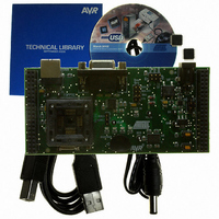
ATSTK526
Description
KIT STARTER FOR AT90USB82/162
Manufacturer
Atmel
Series
AVR®r
Type
MCUr
Specifications of ATSTK526
Contents
Starter Kit Board, Power Supply, Cable and Software
Processor To Be Evaluated
AT90USB82/162
Data Bus Width
8 bit
Interface Type
RS-232, USB
Silicon Manufacturer
Atmel
Core Architecture
AVR
Silicon Core Number
AT90USB82, AT90USB162
Kit Contents
Board Docs
Rohs Compliant
Yes
For Use With/related Products
AT90USB162, AT90USB82
For Use With
ATSTK500 - PROGRAMMER AVR STARTER KIT
Lead Free Status / RoHS Status
Lead free / RoHS Compliant


7709B–AVR–07/08
Using the STK526
2.8.4
2-20
Programming with STK500
Serial Programming The AT90USB82/162 can be programmed using the serial programming mode from
The AT90USB82/162 can be programmed using ISP capability of the JTAGICE (using
the connector adapter that comes with the programmer). This section explains how to
connect and use the AVR JTAG ICE.
Note:
Figure 2-23 . Connecting AVR JTAG ICE to STK526
The Flash, EEPROM, all Fuse and Lock Bit options ISP-programmable can be
programmed individually or with the sequential automatic programming option.
Note:
STK500 firmware. The software interface (In-System Programming of an external target
system) is integrated in AVR Studio®.
To program the device using ISP from STK500, connect the 6-wire cable between the
ISP6PIN connector of the STK500 board and the ISP connector of the STK526 as
shown in Figure 2-20.
See
Figure 2-20
The SPIEN fuse must be enabled in AT90USB82/162
SPIEN fuse is disabled when using debugWire channel (Section “Debugging”,
page 22)
See AVR Studio® on-line Help for information.
to see connection example for ISP with STK500.
STK526 rev. B Hardware User Guide
to allow ISP operation. The
Related parts for ATSTK526
Image
Part Number
Description
Manufacturer
Datasheet
Request
R

Part Number:
Description:
DEV KIT FOR AVR/AVR32
Manufacturer:
Atmel
Datasheet:

Part Number:
Description:
INTERVAL AND WIPE/WASH WIPER CONTROL IC WITH DELAY
Manufacturer:
ATMEL Corporation
Datasheet:
Part Number:
Description:
Low-Voltage Voice-Switched IC for Hands-Free Operation
Manufacturer:
ATMEL Corporation
Datasheet:
Part Number:
Description:
MONOLITHIC INTEGRATED FEATUREPHONE CIRCUIT
Manufacturer:
ATMEL Corporation
Datasheet:
Part Number:
Description:
AM-FM Receiver IC U4255BM-M
Manufacturer:
ATMEL Corporation
Datasheet:
Part Number:
Description:
Monolithic Integrated Feature Phone Circuit
Manufacturer:
ATMEL Corporation
Datasheet:
Part Number:
Description:
Multistandard Video-IF and Quasi Parallel Sound Processing
Manufacturer:
ATMEL Corporation
Datasheet:
Part Number:
Description:
High-performance EE PLD
Manufacturer:
ATMEL Corporation
Datasheet:
Part Number:
Description:
8-bit Flash Microcontroller
Manufacturer:
ATMEL Corporation
Datasheet:
Part Number:
Description:
2-Wire Serial EEPROM
Manufacturer:
ATMEL Corporation
Datasheet: