ATSTK526 Atmel, ATSTK526 Datasheet - Page 16
ATSTK526
Manufacturer Part Number
ATSTK526
Description
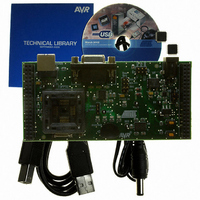
KIT STARTER FOR AT90USB82/162
Manufacturer
Atmel
Series
AVR®r
Type
MCUr
Specifications of ATSTK526
Contents
Starter Kit Board, Power Supply, Cable and Software
Processor To Be Evaluated
AT90USB82/162
Data Bus Width
8 bit
Interface Type
RS-232, USB
Silicon Manufacturer
Atmel
Core Architecture
AVR
Silicon Core Number
AT90USB82, AT90USB162
Kit Contents
Board Docs
Rohs Compliant
Yes
For Use With/related Products
AT90USB162, AT90USB82
For Use With
ATSTK500 - PROGRAMMER AVR STARTER KIT
Lead Free Status / RoHS Status
Lead free / RoHS Compliant


2.6
2.6.1
2.6.2
STK526 rev. B Hardware User Guide
On-board Resources
Joystick
LEDs
The 4+1 ways joystick is convenient for developing input device (USB) application: it
can easily emulate mouse movements, keyboard inputs, etc.
Closing a switch causes the corresponding signal to be pulled low, while releasing (not
pressed) causes an H.Z state on the signal. The user must enable internal pull-ups on
the input pins, removing the need for an external pull-up resistors on the switch.
Figure 2-15 . Joystick Schematic
Figure 2-16 . Joystick Implementation
The STK526 includes 4 green LEDs implemented on one line. They are connected to
the low nibble of “Port D” of AT90USB82/162 (PORTD[3..0]).
To turn ON one LED, the corresponding port pin must drive a high level. To turn OFF
one LED, the corresponding port pin must drive a low level. It is the opposite method
used in STK500.
Figure 2-17 . STK526 LEDs
1
1
1
2
2
2
SW3
SW3
SW3
TPA511G
TPA511G
TPA511G
Com1
Com1
Com1
Com2
Com2
Com2
Select
Select
Select
Down
Down
Down
Right
Right
Right
Lef t
Lef t
Lef t
Up
Up
Up
5
5
5
7
7
7
3
3
3
6
6
6
4
4
4
PB0
P
PB4
PB5
PB6
PB7
PB[7..0]
PB[7..0]
PB[7..0]
Using the STK526
7709B–AVR–07/08
2-15
Related parts for ATSTK526
Image
Part Number
Description
Manufacturer
Datasheet
Request
R

Part Number:
Description:
DEV KIT FOR AVR/AVR32
Manufacturer:
Atmel
Datasheet:

Part Number:
Description:
INTERVAL AND WIPE/WASH WIPER CONTROL IC WITH DELAY
Manufacturer:
ATMEL Corporation
Datasheet:
Part Number:
Description:
Low-Voltage Voice-Switched IC for Hands-Free Operation
Manufacturer:
ATMEL Corporation
Datasheet:
Part Number:
Description:
MONOLITHIC INTEGRATED FEATUREPHONE CIRCUIT
Manufacturer:
ATMEL Corporation
Datasheet:
Part Number:
Description:
AM-FM Receiver IC U4255BM-M
Manufacturer:
ATMEL Corporation
Datasheet:
Part Number:
Description:
Monolithic Integrated Feature Phone Circuit
Manufacturer:
ATMEL Corporation
Datasheet:
Part Number:
Description:
Multistandard Video-IF and Quasi Parallel Sound Processing
Manufacturer:
ATMEL Corporation
Datasheet:
Part Number:
Description:
High-performance EE PLD
Manufacturer:
ATMEL Corporation
Datasheet:
Part Number:
Description:
8-bit Flash Microcontroller
Manufacturer:
ATMEL Corporation
Datasheet:
Part Number:
Description:
2-Wire Serial EEPROM
Manufacturer:
ATMEL Corporation
Datasheet: