CT-161-CD Fujitsu Semiconductor America Inc, CT-161-CD Datasheet - Page 11
CT-161-CD
Manufacturer Part Number
CT-161-CD
Description
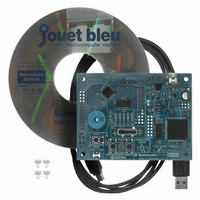
KIT 16LX FOR MB90F387
Manufacturer
Fujitsu Semiconductor America Inc
Series
F²MC-16LXr
Type
MCUr
Specifications of CT-161-CD
Contents
Board, Cable, CD
For Use With/related Products
MB90F387S
Lead Free Status / RoHS Status
Lead free / RoHS Compliant
Other names
865-1103
Available stocks
Company
Part Number
Manufacturer
Quantity
Price
Company:

Part Number:
CT-161-CD
Manufacturer:
Fujitsu Semiconductor America
Quantity:
135


Do Not Exceed Maximum Rating (preventing “latch up”)
Handling Unused Pins
Using External Clock
Notes When Using No Sub Clock
About Power Supply Pins
Crystal Oscillator Circuit
Caution on Operations during PLL Clock Mode
HANDLING DEVICES
• On a CMOS IC, latch-up may occur when applying a voltage higher than Vcc or a voltage lower than Vss to
• Latch-up causes drastic increase of power current, which may lead to destruction of elements by heat. Extreme
• When turning on and off analog power source, take extra care not to apply an analog power voltages (AVcc
• Leaving unused input pins open may cause permanent destruction by malfunction or latch-up. Apply pull-up
• When using an external clock, drive only X0 pin and leave X1 pin open. An example of using an external clock
• If an oscillator is not connected to X0A and X1A pin, apply pull-down resistor to X0A pin and leave X1A pin open.
• If two or more Vcc and Vss exist, the pins that should be at the same potential are connected to each other
• Pay attention to connect a power supply to Vcc and Vss of MB90385 series device in a lowest-possible
• Near pins of MB90385 series device, connecting a bypass capacitor is recommended at 0.1 F across Vcc
• Noises around X0 and X1 pins cause malfunctions on a MB90385 series device. Design a print circuit so that
• Print circuit designing that surrounds X0 and X1 pins with grounding wires, which ensures stable operation,
• If the PLL clock mode is selected, the microcontroller attempt to be working with the self-oscillating circuit even
Using external clock
input or output pin, which has no middle or high withstand voltage. Latch-up may also occur when a voltage
exceeding maximum rating is applied across Vcc and Vss.
caution must be taken not to exceed maximum rating.
and AVR) and analog input voltage that are higher than digital power voltage (Vcc).
or pull-down process to the unused pins using resistors of 2 k or higher. Leave unused input pins open under
output status, or process as input pins if they are under input status.
is shown below.
inside the device. For reducing unwanted emissions and preventing malfunction of strobe signals caused by
increase of ground level, however, be sure to connect the Vcc and Vss pins to the power source and the ground
externally.
impedance.
and Vss.
X0 and X1 pins, an crystal oscillator (or a ceramic oscillator), and bypass capacitor to the ground become as
close as possible to each other. Furthermore, avoid wires to X0 and X1 pins crossing each other as much as
possible.
is strongly recommended.
when there is no external oscillator or external clock input is stopped. Performance of this operation, however,
cannot be guaranteed.
Open
X0
X1
MB90385 series
MB90385 Series
11
Related parts for CT-161-CD
Image
Part Number
Description
Manufacturer
Datasheet
Request
R

Part Number:
Description:
IC POWER SUPPLY MONITOR 8SOP
Manufacturer:
Fujitsu Semiconductor America Inc
Datasheet:
Part Number:
Description:
IC POWER SUPPLY MONITOR 8SOP
Manufacturer:
Fujitsu Semiconductor America Inc
Datasheet:

Part Number:
Description:
IC MCU 60K FLASH 2KB RAM 52LQFP
Manufacturer:
Fujitsu Semiconductor America Inc
Datasheet:

Part Number:
Description:
IC MCU 32BIT 256KB FLASH 120LQFP
Manufacturer:
Fujitsu Semiconductor America Inc
Datasheet:
Part Number:
Description:
IC CTLR TOUCH SENSOR 12CH 30SSOP
Manufacturer:
Fujitsu Semiconductor America Inc
Datasheet:

Part Number:
Description:
IC CTLR TOUCH SENSOR 12CH 40QFN
Manufacturer:
Fujitsu Semiconductor America Inc
Datasheet:
Part Number:
Description:
SYNTHESIZER PLL DUAL INP 20SSOP
Manufacturer:
Fujitsu Semiconductor America Inc
Datasheet:

Part Number:
Description:
SYNTHESZR PLL 1.1GHZ DUAL 16SSOP
Manufacturer:
Fujitsu Semiconductor America Inc
Datasheet:

Part Number:
Description:
IC SSCG EMI RED 8-SOIC
Manufacturer:
Fujitsu Semiconductor America Inc
Datasheet:

Part Number:
Description:
IC SSCG EMI RED 8-TSSOP
Manufacturer:
Fujitsu Semiconductor America Inc
Datasheet:

Part Number:
Description:
IC SSCG EMI RED 8-SOP
Manufacturer:
Fujitsu Semiconductor America Inc
Datasheet:

Part Number:
Description:
SYNTHESIZER PLL 2.5GHZ 16SSOP
Manufacturer:
Fujitsu Semiconductor America Inc
Datasheet:
Part Number:
Description:
SYNTHESIZER PLL 1.2GHZ 16SSOP
Manufacturer:
Fujitsu Semiconductor America Inc
Datasheet:

Part Number:
Description:
SYNTHESIZER PLL 2.5GHZ 16BCC
Manufacturer:
Fujitsu Semiconductor America Inc
Datasheet:

Part Number:
Description:
IC SSCG EMI RED 8-SOP
Manufacturer:
Fujitsu Semiconductor America Inc
Datasheet: