101-1274 Rabbit Semiconductor, 101-1274 Datasheet
101-1274
Specifications of 101-1274


Related parts for 101-1274


101-1274 Summary of contents
Page 1
MiniCore RCM5700/RCM6700 C-Programmable Ethernet Core Module User’s Manual 90001191_B ...
Page 2
MiniCore RCM5700/RCM6700 User’s Manual Part Number 90001191 ©2008–2010 Digi International Inc. • All rights reserved. Digi International reserves the right to make changes and improvements to its products without providing notice. Trademarks Rabbit, MiniCore, and Dynamic C are registered trademarks ...
Page 3
Introduction 1.1 RCM5700/RCM6700 Features ......................6 1.2 Advantages of the RCM5700 and RCM6700 8 1.3 Development and Evaluation Tools ...............9 1.3.1 Standard Development Kit ....................9 1.3.2 Deluxe Development Kit .......................9 1.3.3 Software ...............................................10 1.3.4 Online Documentation .........................10 2. Getting Started ...
Page 4
... F.4 Running TCP/IP Sample Programs .............98 F.4.1 How to Set IP Addresses in the Sample Programs .....................................................99 F.4.2 How to Set Up your Computer for Direct Connect .....................................................100 F.5 Run the PINGME.C Sample Program .......101 F.6 Running Additional Sample Programs With Di- rect Connect ....................................................102 F.7 Where From Here?.......................103 Appendix G. Power Supply G ...
Page 5
The RCM5700 and RCM6700 are compact modules in a mini PCI Express form factor, and incorporate the powerful Rabbit® 5000 and 6000 microprocessors with integrated 10/100Base-T Ethernet func- tionality and onchip SRAM. The Rabbit® 5000 and 6000 microproces- sor features ...
Page 6
RCM5700/RCM6700 Features • Small size: ranges from 1.20" × 2.00" × 0.12" (30 mm × × 3 mm) for the RCM5700/ RCM6700 model to 1.20" × 2.00" × 0.73" (30 mm × × 19 mm) ...
Page 7
The RCM5700 and RCM5750 models already have an Ethernet PHY device, the Integrated Cir- cuit Systems ICS1893BK. The RCM5710 and RCM5760 are identical to the RCM5700 and RCM5750 respectively, except that they have an integrated 10/100 Base-T magnetic RJ-45 jack ...
Page 8
All RCM5700/RCM6700 models are programmed through a USB connector on the motherboard using a USB cable supplied with the Development Kit. The RCM5750/RCM5760 may also be programmed remotely over an Ethernet link using the Remote Program Update library with Dynamic ...
Page 9
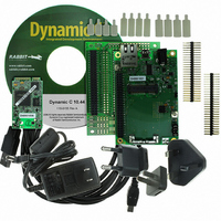
Development and Evaluation Tools 1.3.1 Standard Development Kit The RCM5700/RCM6700 Standard Development Kit contains the hardware essentials you will need to use your RCM5700 or RCM6700 module. These items are supplied in the standard ver- sion of the Development ...
Page 10
Software The RCM5700/RCM5710 is programmed using version 10.44 or later of Dynamic C; the RCM5750/RCM5760 requires version 10.56 or later of Dynamic C; and the RCM6700 family requires version 10.64 or later. A compatible version is included on the ...
Page 11
This chapter describes the RCM5700/RCM6700 hardware in more detail, and explains how to set up and use the accompanying Interface Board. NOTE: This chapter (and this manual) assume that you have the RCM5700/RCM6700 Develop- ment Kit. If you purchased an ...
Page 12
Hardware Connections There are three steps to connecting the Interface Board for use with Dynamic C and the sample programs: 1. Insert standoffs/connectors on the Interface Board. 2. Install the MiniCore module on the Interface Board. 3. Connect the ...
Page 13
Step 2 — Install Module on Interface Board Position the MiniCore module with the edge connectors facing the mini PCI Express socket J1A at an angle as shown in Figure 2-3 below. Insert the edge connectors into the mini ...
Page 14
Should you need to remove the MiniCore module, use two fingernails to hold back the spring clip at J1B from the two MiniCore corners, lift up the edge of the MiniCore above J1B, then pull the MiniCore away to remove ...
Page 15
Step 3 — Connect USB Cable The USB cable connects the RCM5700/RCM6700 to the PC running Dynamic C to download programs and to monitor the MiniCore module during debugging. It also supplies power to the Interface Board and the ...
Page 16
Alternate Power Supply Connections — Deluxe Development Kit The deluxe Development Kit contains a separate AC adapter that may be used to supply power to the Interface Board and the RCM5700/RCM6700 when the USB cable is not connected or ...
Page 17
Starting Dynamic C If you already have Dynamic C installed, you are now ready to test your programming connec- tions by running a sample program. Start Dynamic C by double-clicking on the Dynamic C icon on your desktop or ...
Page 18
Where From Here? If the sample program ran fine, you are now ready other sample programs and to develop your own applications. The source code for the sample programs is provided to ...
Page 19
R To develop and debug programs for the RCM5700/RCM6700 (and for all other Rabbit hardware), you must install and use Dynamic C. This chapter provides a tour of its major features with respect to the RCM5700/RCM6700. 3.1 Introduction To ...
Page 20
Sample Programs Of the many sample programs included with Dynamic C, several are specific to the RCM5700/RCM6700. These programs will be found in the folder, depending on your MiniCore model. Sample programs in the PLES\RCM6700 folder one level up ...
Page 21
The Digital I/O accessory board needs to be installed to run the sample programs. This accessory board is included only with the Deluxe Develop- TOSERIAL.C ment Kit. To install the Digital I/O accessory board, insert the strip of header pins ...
Page 22
The sample program is in the SERIALTOSERIAL.C SAMPLES\RCM6700\SERIAL —monitors switches S1, S2, S3, and S4 on the Digital I/O accessory • SERIALTOSERIAL.C board and lights LEDs DS1–DS4 when the corresponding pushbutton switch is pressed. LEDs DS1–DS2 on the Digital I/O ...
Page 23
The Serial Communication accessory board needs to be installed to run the following serial sam- ple program in the SAMPLES\RCM5700\SERIAL ing on your MiniCore model. This accessory board is included only with the Deluxe Development Kit. To install the Serial ...
Page 24
Once you have loaded and executed these sample programs and have an understanding of how Dynamic C and the RCM5700/RCM6700 modules interact, you can move on and try the other sample programs, or begin developing your own application. 3.2.1 Use ...
Page 25
Chapter 4 describes the hardware components and principal hardware subsys- tems of the RCM5700/RCM6700. Appendix A, “RCM5700/RCM6700 Spec- ifications,” provides complete physical and electrical specifications. Figure 4-8 shows the Rabbit-based subsystems designed into the RCM5700/RCM6700. Figure 4-8. RCM5700/RCM6700 Subsystems MiniCore ...
Page 26
RCM5700/RCM6700 Digital Inputs and Outputs Figure 4-9 shows the RCM5700/RCM6700 pinouts for the edge connector. Figure 4-9. RCM5700/RCM6700 Pinouts The edge connectors are designed to interface with a 52-pin mini PCI Express socket. Pin 8 has different functionality between ...
Page 27
Figure 4-10 shows the use of the Rabbit 5000/6000 microprocessor ports in the RCM5700/ RCM6700 modules. Figure 4-10. Use of Rabbit 5000/6000 Ports The ports on the Rabbit microprocessor used in the RCM5700/RCM6700 are configurable, and so the defaults can ...
Page 28
Table 4-3. RCM5700/RCM6700 Pinout Configurations Pin Pin Name 1 GND 2 +3 Tx+ 4 Rx+ 5 Tx– 6 Rx– Ethernet 7 LNK ACT (RCM5700) 8 +2.5V (RCM6700) 9 PE0 Input/Output 10 PE1 Input/Output 11 PE2 Input/Output 12 PE3 ...
Page 29
Table 4-3. RCM5700/RCM6700 Pinout Configurations Pin Pin Name 13 PE5 Input/Output 14 PE6 Input/Output 15 PE7 Input/Output 16 /RESET_IN Input 17 PD0 Input/Output 18 PD1 Input/Output MiniCore RCM5700/RCM6700 User’s Manual Default Use Alternate Use I/O Strobe I5 INT1 PWM1 RXB/RCLKE ...
Page 30
Table 4-3. RCM5700/RCM6700 Pinout Configurations Pin Pin Name 19 PD2 Input/Output 20 PD3 Input/Output 21 PC0 Input/Output 22 PC1 Input/Output 23 PC2 Input/Output 24 PC3 Input/Output 25 PC4 Input/Output 26 PC5 Input/Output MiniCore RCM5700/RCM6700 User’s Manual Default Use Alternate Use ...
Page 31
Table 4-3. RCM5700/RCM6700 Pinout Configurations Pin Pin Name 27 PB0 Input/Output 28 /RESET Reset output 29 PB2 Input/Output 30 PB3 Input/Output 31 PB4 Input/Output 32 PB5 Input/Output 33 PB6 Input/Output 34 PB7 Input/Output 35–42 PA[0:7] Input/Output 43 /IORD Output 44 ...
Page 32
Table 4-3. RCM5700/RCM6700 Pinout Configurations Pin Pin Name 47 STATUS Output 48 PC6 Input/Output 49 SMODE Input 50 PC7 Input/Output 51 GND 52 +3.3 V MiniCore RCM5700/RCM6700 User’s Manual Default Use Alternate Use TXA/TXE I/O Strobe I6 PWM2 RXA/TXA/RXE I/O ...
Page 33
Memory I/O Interface The Rabbit 5000 address lines (A0–A19) and data lines (D0–D7) are routed to the onboard flash memory chip. I/O write (/IOWR) and I/O read (/IORD) are available for interfacing to external devices. Parallel Port A can ...
Page 34
Serial Communication The RCM5700/RCM6700 board does not have any serial level converters directly on the board. However, an Ethernet or other serial interface may be incorporated on the board the MiniCore is mounted on. For example, the Serial Communication ...
Page 35
Table 4-4 summarizes the possible parallel port pins for the serial ports and their clocks. Table 4-4. Rabbit 5000 and 6000 Serial Port and Clock Pins TXA Serial Port A RXA SCLKA TXB Serial Port B RXB SCLKB TXC Serial ...
Page 36
Ethernet PHY All RCM5700/RCM6700 models have an Ethernet PHY, which can either be accessed through the Interface Board or directly on the RCM5710/5760/6710/6760. The PHY connections or inte- grated 10/100Base-T connections on MiniCores with an on-board RJ-45 jack are ...
Page 37
Programming Modes The USB cable is used to connect the programming port of the RCM5700/RCM6700 USB port via the Interface Board. Whenever the MiniCore is reset, the operating mode is determined by the state of the ...
Page 38
Standalone Operation of the RCM5700/RCM6700 The RCM5700/RCM6700 must be programmed via the Interface Board or via a similar arrange- ment on a customer-supplied board. Once the MiniCore has been programmed successfully, reset the MiniCore. The MiniCore may be reset ...
Page 39
Memory 4.5.1 RAM RCM5700 boards have 128KB of onchip SRAM on the Rabbit 5000 microprocessor. The RCM5750/RCM5760 models also have 512KB of external SRAM. RCM6700 boards have 1MB of onchip RAM and 32KB of onchip battery-backable SRAM on the ...
Page 40
Dynamic integrated development system for writing embedded software. It runs on a Windows-based PC and is designed for use with single-board computers and other devices based on the Rabbit micro- processor. Chapter 5 describes the libraries and ...
Page 41
Dynamic C has a number of standard features. • Full-feature source and/or assembly-level debugger, no in-circuit emulator required. • Royalty-free TCP/IP stack with source code and most common protocols. • Hundreds of functions in source-code libraries and sample programs: ...
Page 42
Dynamic C Function Calls 5.2.1 Digital I/O The RCM5700/RCM6700 was designed to interface with other systems, and so there are no driv- ers written specifically for the Rabbit 5000/6000 I/O. The general Dynamic C read and write functions allow ...
Page 43
RCM5700/RCM6700 Cloning The RCM5700/RCM6700 does not have a programming header, and is programmed through the USB connection on the Interface Board. Rabbit’s Cloning Board does not support cloning through a USB connection. If there is a need to copy ...
Page 44
A PPENDIX Appendix A provides the specifications for the RCM5700 and RCM6700. MiniCore RCM5700/RCM6700 User’s Manual A. RCM5700/RCM6700 S PECIFICATIONS rabbit.com 44 ...
Page 45
A.1 Electrical and Mechanical Characteristics Figures A-1(a) and A-1(b) show the mechanical dimensions for the RCM5700/RCM6700 and RCM5760/RCM6760. The related dimensions for the RCM5710/6710 and RCM5750/RCM6750 are listed in Table A-1. (All measurements are in inches followed by millimeters enclosed ...
Page 46
Figure A-1(b). RCM5760/RCM6760 Dimensions MiniCore RCM5700/RCM6700 User’s Manual rabbit.com 46 ...
Page 47
It is recommended that you allow for an “exclusion zone” of 0.08" (2 mm) around the RCM5700/RCM6700 top and bottom and 0.04" (1 mm) around the three non-connector edges when the RCM5700/RCM6700 is incorporated into an assembly that includes other ...
Page 48
Table A-1 lists the electrical, mechanical, and environmental specifications for the RCM5700. Table A-1. RCM5700 Specifications Parameter Microprocessor EMI Reduction Ethernet Port Flash Memory (program) Flash Memory (mass data storage) External SRAM SRAM Connection for user-supplied backup Backup Battery up ...
Page 49
Table A-1. RCM5700 Specifications Parameter Input Capture Quadrature Decoder Power Operating Temperature Humidity Connectors Board Size (30 mm × MiniCore RCM5700/RCM6700 User’s Manual RCM5700 RCM5710 2-channel input capture can be used to time input signals from various port ...
Page 50
Table A-2 lists the electrical, mechanical, and environmental specifications for the RCM6700. Table A-2. RCM6700 Specifications Parameter Microprocessor EMI Reduction Ethernet Port Flash Memory (mass data storage) External SRAM RAM SRAM 32KB (Rabbit 6000 onchip, battery-backable) Backup Battery up to ...
Page 51
Table A-2. RCM6700 Specifications Parameter Quadrature Decoder 210 mA @ 3.3V Power 120 mA @ 3.3V (typical -- without Operating Temperature Humidity Connectors Board Size (30 mm × MiniCore RCM5700/RCM6700 User’s Manual RCM6700 RCM6710 2-channel quadrature decoder accepts ...
Page 52
A.1.1 mini PCI Express Connector Design Recommendations The MiniCore is mounted on the Interface Board via a mini PCI Express connector and a corre- sponding locking latch connector. These are offered by manufacturers as a matched set, although in some ...
Page 53
Other manufacturers such as Molex offer similar connectors and latches, but these can have dif- ferent mechanical structures and PCB footprints to what we use on the Interface Board. Table A-4 lists a pair of matched Molex parts that might ...
Page 54
... RCM5700/RCM6700. The Rabbit store sells an accessory kit (Part No. 101-1306) with the standoffs, screws, and mini PCI Express connector needed to mount an MiniCore module using the footprint shown in Figure A-4. The heights of the mini PCI Express connector and the associated standoffs in the accessory kit are shown in millimeters at right ...
Page 55
A.3 Jumper Configurations Figure A-5 shows the header locations used to configure the various RCM5700/RCM6700 options via jumpers. Note that some early versions of the RCM5700 model sold in 2008 and 2009 do not have jumper locations JP2–JP5 — this ...
Page 56
Table A-7. RCM6700 Jumper Configurations Header Description JP2 Tx+ JP3 Tx– JP4 Rx– JP5 Rx+ NOTE: The jumper connections are made using 0 surface-mounted resistors. MiniCore RCM5700/RCM6700 User’s Manual Pins Connected 1–2 Tx+ to RJ-45 jack (J1) 2–3 Tx+ ...
Page 57
A Appendix B describes the features and accessories of the Interface Board, and explains the use of the Interface Board to demonstrate the RCM5700 and RCM6700. The Interface Board has power-supply con- nections and a USB interface to program either ...
Page 58
B.1 Introduction The Interface Board included in the Development Kit makes it easy to connect MiniCore module to a power supply and a PC workstation for development. It also provides an Ethernet port. The Interface Board is shown below in ...
Page 59
B.1.1 Interface Board Features —Power is supplied to the Interface Board either from the PC via the USB • Power Connection connection or through a power supply jack, J6. A chip at U4 disconnects the USB power sup- ply from ...
Page 60
B.2 Mechanical Dimensions and Layout Figure B-2 shows the mechanical dimensions and layout for the Interface Board. All measurements are in inches followed by millimeters enclosed in parentheses. Figure B-2. Interface Board Dimensions Table B-1 lists the electrical, mechanical, and ...
Page 61
B.2.1 Headers The Interface Board has a header socket at J2 for physical connection to other boards × 25 SMT header socket with a 0.1" pin spacing. Figure B-3 shows the layout of another board to ...
Page 62
B.3 Ethernet B.3.1 RJ-45 The Ethernet filter circuit is different between the Rabbit 5000 and Rabbit 6000 Ethernet designs RJ-45 jack is present on the MiniCore, then the appropriate circuitry is on the MiniCore. If the interface board ...
Page 63
B.4 Power Supply The MiniCore requires a regulated 3.15 V – 3. power source to operate. Depending on the amount of current required by the application, different regulators can be used to supply this voltage. The Interface Board ...
Page 64
B.5 Using the Interface Board The Interface Board is also a demonstration board. It can be used to demonstrate the functionality of the MiniCore right out of the box without any modifications to either board. The Interface Board comes with ...
Page 65
B.5.1 Add Additional Boards The Prototyping Board and the two accessory boards included with the Deluxe Development Kit may be installed on the Interface Board as shown in Figure B-6. Figure B-6. Install Additional Boards on Interface Board 1. Insert ...
Page 66
B.6 Interface Board Jumper Configurations Figure B-7 shows the header locations used to configure the various Interface Board options via jumpers. Figure B-7. Location of Configurable Jumpers on Interface Board Table B-3 lists the configuration options using either jumpers or ...
Page 67
A PPENDIX Appendix C describes the features and accessories of the Prototyping Board, and explains the use of the Prototyping Board to build proto- types of your own circuits. The Prototyping Board mounts on the Inter- face Board from which ...
Page 68
C.1 Introduction The Prototyping Board included in the Development Kit provides a prototyping area for more advanced hardware development. The Prototyping Board is shown below in Figure C-1, with its main features identified. C.1.1 Prototyping Board Features —Power is supplied ...
Page 69
C.2 Mechanical Dimensions and Layout Figure C-2 shows the mechanical dimensions and layout for the Prototyping Board. Figure C-2. Prototyping Board Dimensions (All measurements are in inches followed by millimeters enclosed in parentheses.) MiniCore RCM5700/RCM6700 User’s Manual rabbit.com 69 ...
Page 70
Table C-1 lists the electrical, mechanical, and environmental specifications for the Prototyping Board. Table C-1. Prototyping Board Specifications Parameter Board Size Operating Temperature Humidity Operating Voltage Current Draw from Interface Board (excluding user-added circuits) Prototyping Area Connectors Standoffs/Spacers MiniCore RCM5700/RCM6700 ...
Page 71
C.2.1 Headers The Prototyping Board has a header socket at J2 for physical connection to other boards above it, and a header socket at J12 on the bottom side to connect to boards below it. J2 and J12 are 2 ...
Page 72
C.3 Using the Prototyping Board The Prototyping Board provides the user with MiniCore connection points brought out conveniently to labeled points below header J2. The pinouts for header socket J2 are shown in Figure C-4. There is a 1.7" × ...
Page 73
C.3.1 Add Additional Boards The Prototyping Board and the two accessory boards included with the Deluxe Development Kit may be installed on the Interface Board as shown in Figure C-5. 1. Insert the header strip into header socket J2 on ...
Page 74
A PPENDIX Appendix D describes the features and accessories of the Digital I/O accessory board, and explains how to use the Digital I/O accessory board. The Digital I/O accessory board mounts on the Interface Board or other board already installed ...
Page 75
D.1 Introduction The Digital I/O accessory board included in the Deluxe Development Kit provides Pushbutton switches and LEDs to use in conjunction with selected sample programs. The Digital I/O acces- sory board is shown below in Figure D-1, with its ...
Page 76
D.2 Mechanical Dimensions and Layout Figure D-2 shows the mechanical dimensions and layout for the Digital I/O accessory board. Figure D-2. Digital I/O Accessory Board Dimensions (All measurements are in inches followed by millimeters enclosed in parentheses.) Table D-1 lists ...
Page 77
D.2.1 Headers The Digital I/O accessory board has a header socket at J2 for physical connection to other boards above it, and a header socket at J12 on the bottom side to connect to boards below it. J2 and J12 ...
Page 78
D.3 Using the Digital I/O Accessory Board The Digital I/O accessory board provides the user with MiniCore connection points brought out conveniently to labeled points below header J2. The pinouts for header socket J2 are shown in Figure D-4. MiniCore ...
Page 79
D.3.1 Configuration The pushbutton switches may be configured active high (pulled down) or active low (pulled up) via jumper settings on header JP7 for the four switches installed. Jumpers on JP12 may be set similar way after ...
Page 80
Table D-2. Digital I/O Accessory Board Switch/LED Connection Options Default MiniCore Switch/LED Signal PA4 PA5 PA6 PA7 PB0 PB1 PB2 PB3 PA0 PA1 PA2 PA3 * Switches S1–S4 are pulled high or low via jumpers on header JP7. † Switches ...
Page 81
D.3.2 Add Additional Boards The Prototyping Board and the two accessory boards included with the Deluxe Development Kit may be installed on the Interface Board as shown in Figure D-7. 1. Insert the header strip into header socket J2 on ...
Page 82
A PPENDIX Appendix E describes the features and accessories of the Serial Com- munication accessory board, and explains how to use the Serial Com- munication accessory board. The Serial Communication accessory board mounts on the Interface Board or other board ...
Page 83
E.1 Introduction The Serial Communication accessory board included in the Deluxe Development Kit provides two 3-wire serial ports to use in conjunction with selected sample programs. The Serial Commu- nication accessory board is shown below in Figure E-1, with its ...
Page 84
E.2 Mechanical Dimensions and Layout Figure E-2 shows the mechanical dimensions and layout for the Serial Communication accessory board. (All measurements are in inches followed by millimeters enclosed in parentheses.) Figure E-2. Serial Communication Accessory Board Dimensions Table E-1 lists ...
Page 85
E.2.1 Headers The Serial Communication accessory board has a header socket at J2 for physical connection to other boards above it, and a header socket at J12 on the bottom side to connect to boards below it. J2 and J12 ...
Page 86
E.3 Using the Serial Communication Accessory Board The Serial Communication accessory board provides the user with MiniCore connection points brought out conveniently to labeled points below header J2. The pinouts for header socket J2 and the RS-232 headers at J3 ...
Page 87
E.3.1 Configuration Serial Ports C and D are brought out as 3-wire RS-232 serial ports on headers J4 and J3 respec- tively. Jumpers may be installed on header JP7 to use header 5-wire RS-232 serial port with ...
Page 88
Figure E-5 shows the locations of the configurable header positions. Figure E-5. Location of Configurable Jumpers on Serial Communication Accessory Board MiniCore RCM5700/RCM6700 User’s Manual rabbit.com 88 ...
Page 89
E.3.2 Add Additional Boards The Prototyping Board and the two accessory boards included with the Deluxe Development Kit may be installed on the Interface Board as shown in Figure E-6. 1. Insert the header strip into header socket J2 on ...
Page 90
PPENDIX F.1 TCP/IP Connections Programming and development can be done with the MiniCore without connecting the Ethernet port to a network. However, if you will be running the sample programs that use the Ethernet capability or will ...
Page 91
The following options require more care in address selection and testing actions, as conflicts with other users, servers and systems can occur: LAN — Connect the Interface Board’s Ethernet port to an existing LAN, preferably one to • which the ...
Page 92
F.2 TCP/IP Primer on IP Addresses Obtaining IP addresses to interact over an existing, operating, network can involve a number of complications, and must usually be done with cooperation from your ISP and/or network systems administrator. For this reason, it ...
Page 93
If your system administrator can give you an Ethernet cable along with its IP address, the netmask and the gateway address, then you may be able to run the sample programs without having to setup a direct connection between your ...
Page 94
F.2.1 IP Addresses Explained IP (Internet Protocol) addresses are expressed as 4 decimal numbers separated by periods, for example: 216.103.126.155 10.1.1.6 Each decimal number must be between 0 and 255. The total IP address is a 32-bit number consist- ing ...
Page 95
F.2.2 How IP Addresses are Used The actual hardware connection via an Ethernet uses Ethernet adapter addresses (also called MAC addresses). These are 48-bit addresses and are unique for every Ethernet adapter manufac- tured. In order to send a packet ...
Page 96
F.2.3 Dynamically Assigned Internet Addresses In many instances, devices on a network do not have fixed IP addresses. This is the case when, for example, you are assigned an IP address dynamically by your dial-up Internet service provider (ISP) or ...
Page 97
F.3 Placing Your Device on the Network In many corporate settings, users are isolated from the Internet by a firewall and/or a proxy server. These devices attempt to secure the company from unauthorized network traffic, and usually work by disallowing ...
Page 98
F.4 Running TCP/IP Sample Programs We have provided a number of sample programs demonstrating various uses of TCP/IP for net- working embedded systems. These programs require you to connect your PC and the MiniCore module together on the same network. ...
Page 99
F.4.1 How to Set IP Addresses in the Sample Programs With the introduction of Dynamic C 7.30 we have taken steps to make it easier to run many of our sample programs. You will see a configuration from a list ...
Page 100
... NOTE: Your network interface card will likely have a different name. 3. Now select the IP Address on “Properties” to assign an IP address to your computer (this will disable “obtain an IP address automatically”): IP Address : 10.10.6.101 Netmask : 255.255.255.0 Default gateway : 10.10.6.1 4. Click or to exit the various dialog boxes. ...
Page 101
... The next step is to ping the module from your PC. This can be done by bringing up the MS-DOS window and running the pingme program: ping 10.10.6.101 or by Start > Run and typing the entry ping 10 ...
Page 102
F.6 Running Additional Sample Programs With Direct Connect The sample programs discussed here are in the Dynamic C folder. PLES\RCM6700\TCPIP —The Digital I/O accessory board must be installed with the jumpers set up as • BROWSELED.C shown below to run ...
Page 103
Bits per second: Data bits: 8 Parity: None Stop bits: 1 Flow control: None As long as you have not modified the following server address in your Web browser to bring up the Web page served by the sample ...
Page 104
Appendix G provides information on the current requirements of the RCM5700/RCM6700, and includes some background on the chip select circuit used in power management. G.1 Power Supplies The RCM5700/RCM6700 requires a regulated 3.15 V – 3. power source. ...
Page 105
G.1.1 Battery Backup for the RCM5700/RCM5710 and RCM6700 Family The RCM5700/RCM6700 does not have a battery, but there is provision for a customer-supplied battery to keep the internal Rabbit 5000/6000 real-time clock running on the RCM5700/RCM5710 and RCM6700 family of ...
Page 106
The actual life in your application will depend on the current drawn by components not on the RCM5700/RCM6700 and on the storage capacity of the battery. The RCM5700/RCM6700 does not drain the battery while it is powered up normally. Cycle ...
Page 107
A accessory boards Digital I/O ...........................................................75 configuration options ......................................79 LED outputs ..............................................79 pushbutton switches ..................................79 dimensions ......................................................76 specifications ..................................................76 Serial Communication .........................................83 configuration options ......................................87 RTS/CTS ..................................................87 dimensions ......................................................84 specifications ..................................................84 additional information online documentation ..........................................10 B battery backup battery ...
Page 108
F features Digital I/O accessory board .................................75 Interface Board ....................................................59 Prototyping Board ...............................................68 RCM5700 ..............................................................6 Serial Communication accessory board ..............83 H hardware connections ..............................................12 install RCM5700 on Interface Board ..................13 USB cable ............................................................15 I install additional boards ..............................65, 73, 81 ...
Page 109
... ETHERNET_TO_SERIAL.C ......................102 PINGME.C ...................................................101 USERBLOCK_CLEAR.C ..................................42 USERBLOCK_INFO.C ......................................42 serial communication ..............................................34 function calls .......................................................42 software PACKET.LIB .................................................42 RS232.LIB ......................................................42 Serial Communication accessory board ..................83 features ................................................................83 serial flash software FAT_CONFIG.LIB ........................................43 SFLASH.LIB ..................................................43 serial ports .........................................................34, 35 Ethernet port ........................................................36 programming port ................................................36 Serial Port B manage conflicts with RCM5750/RCM5760 se- rial flash .............................................34 Serial Port E configuration information ..............................34 Serial Port F configuration information ...
Page 110
MiniCore RCM5700/6700 User’s Manual rabbit.com 110 ...
Page 111
MiniCore RCM5700/6700 User’s Manual rabbit.com 111 ...
Page 112
MiniCore RCM5700/6700 User’s Manual rabbit.com 112 ...
Page 113
MiniCore RCM5700/6700 User’s Manual rabbit.com 113 ...
Page 114
MiniCore RCM5700/6700 User’s Manual rabbit.com 114 ...
Page 115
MiniCore RCM5700/6700 User’s Manual rabbit.com 115 ...
Page 116
MiniCore RCM5700/6700 User’s Manual rabbit.com 116 ...
Page 117
MiniCore RCM5700/6700 User’s Manual rabbit.com 117 ...
Page 118
MiniCore RCM5700/6700 User’s Manual rabbit.com 118 ...
Page 119
MiniCore RCM5700/6700 User’s Manual rabbit.com 119 ...