101-1274 Rabbit Semiconductor, 101-1274 Datasheet - Page 62
101-1274
Manufacturer Part Number
101-1274
Description
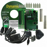
KIT DEV STANDARD RCM5700
Manufacturer
Rabbit Semiconductor
Series
MiniCore™r
Type
MCUr
Datasheet
1.20-101-1306.pdf
(119 pages)
Specifications of 101-1274
Interface Type
Ethernet, SPI
Operating Temperature Range
- 40 C to + 85 C
Product
Modules
Silicon Manufacturer
Rabbit Semiconductor
Silicon Family Name
RabbitCore
Kit Contents
Board
Features
10/100 Base-T Ethernet, Serial To Ethernet Bridge
Development Tool Type
Development Kit
Rohs Compliant
Yes
For Use With/related Products
RCM5700
Lead Free Status / RoHS Status
Contains lead / RoHS non-compliant
Contents
-
Lead Free Status / Rohs Status
Lead free / RoHS Compliant
Other names
316-1151


B.3 Ethernet
B.3.1 RJ-45
The Ethernet filter circuit is different between the Rabbit 5000 and Rabbit 6000 Ethernet designs.
If an RJ-45 jack is present on the MiniCore, then the appropriate circuitry is on the MiniCore. If
the interface board Ethernet RJ-45 is to be used, then a given interface board will support Ethernet
only for either the RCM5700 or RCM6700 family, but not both. The interface board supplied in
the Development Kit is properly configured for the MiniCore in the kit.
B.3.2 RCM6700 LEDs
The RCM6700/RCM6750 only support a single off-board Ethernet status LED, unlike the
RCM5700/RCM5750 which support two (LINK and ACT). The signal used as ACT on the
RCM5700 is replaced with +2.5 V for the Ethernet circuitry on the RCM6700. To provide the
same information, a combined LINK+ACT signal is used: off means no link, on means link, and
blink means activity. The on-board Ethernet LEDs on the RJ-45 jack behave identically in both
the RCM5700 and RCM6700.
If the RCM5700’s two-LED configuration is desired for a RCM6700-based design, the behavior
of the LINK+ACT signal must be changed to just LINK, and a GPIO pin must be assigned as the
ACT signal. The Interface Board is designed to support either PE3 or PE5 as the ACT signal, and
can be configured by defining macros and placing jumpers as shown in Table B-2.
The Ethernet LEDs are under software control on the RCM6700, so other configurations are pos-
sible as well. See the RCM6700-specific section of
details.
MiniCore RCM5700/RCM6700 User’s Manual
Single LED
Dual LEDs,
ACT is PE3
Dual LEDs,
ACT is PE5
Mode
Table B-2. Interface Board Ethernet LED Configuration for RCM6700
LINK off is no link
LINK on is link, blink
off for activity
LINK off is no link
LINK on is link
ACT off is no activity
ACT on is activity
(matches RCM5700)
Behavior
rabbit.com
Setting
JP80
4–6
1–3
4–6
1–2
4–6
LIB\Rabbit4000\TCPIP
None (default behavior)
ENET_ACTIVITY_ON_PE3
ENET_ACTIVITY_ON_PE5
Macros to define
folder for more
62
Related parts for 101-1274
Image
Part Number
Description
Manufacturer
Datasheet
Request
R

Part Number:
Description:
COMPUTER SNGLBD BL2120 FRCTNLOCK
Manufacturer:
Rabbit Semiconductor
Datasheet:

Part Number:
Description:
KIT APPLCTN RABBITCORE RCM4010
Manufacturer:
Rabbit Semiconductor
Datasheet:

Part Number:
Description:
KIT MESH NETWORK ADD-ON RCM4510W
Manufacturer:
Rabbit Semiconductor
Datasheet:

Part Number:
Description:
KIT DEV FOR BL2500 COYOTE
Manufacturer:
Rabbit Semiconductor
Datasheet:

Part Number:
Description:
KIT APPLICATION SIMPLE SENSOR
Manufacturer:
Rabbit Semiconductor
Datasheet:

Part Number:
Description:
KIT DEV RABBITCORE RCM3750
Manufacturer:
Rabbit Semiconductor
Datasheet:

Part Number:
Description:
KIT DEV RABBIT 2000 INT'L
Manufacturer:
Rabbit Semiconductor
Datasheet:
Part Number:
Description:
KIT DEV RABBIT RCM2000 INT'L
Manufacturer:
Rabbit Semiconductor
Datasheet:

Part Number:
Description:
KIT DEVELOPMENT RCM3700 INT'L
Manufacturer:
Rabbit Semiconductor
Datasheet:
Part Number:
Description:
MODULE RABBITCORE RCM3720
Manufacturer:
Rabbit Semiconductor
Datasheet:
Part Number:
Description:
MODULE RABBITCORE RCM3220
Manufacturer:
Rabbit Semiconductor
Datasheet:
Part Number:
Description:
MODULE RABBITCORE RCM3210
Manufacturer:
Rabbit Semiconductor
Datasheet:
Part Number:
Description:
COMPUTER SGL-BOARD OP6600 W/SRAM
Manufacturer:
Rabbit Semiconductor
Datasheet:
Part Number:
Description:
COMPUTER SGL-BD BL2000 SRAM/FLSH
Manufacturer:
Rabbit Semiconductor