101-0587 Rabbit Semiconductor, 101-0587 Datasheet - Page 21
101-0587
Manufacturer Part Number
101-0587
Description
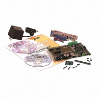
KIT DEV RABBITCORE/RCM3400
Manufacturer
Rabbit Semiconductor
Series
RabbitCore 3000r
Type
MPU Moduler
Datasheet
1.101-0561.pdf
(154 pages)
Specifications of 101-0587
Rohs Status
RoHS non-compliant
Contents
RabbitCore Module, Dev. Board, AC Adapter, Cable and Dynamic C® CD-Rom
Processor To Be Evaluated
RCM3400
Data Bus Width
8 bit
Interface Type
Ethernet
Maximum Operating Temperature
+ 85 C
Minimum Operating Temperature
- 40 C
Operating Supply Voltage
2.8 V to 3.45 V
For Use With/related Products
RCM3400
Lead Free Status / Rohs Status
Lead free / RoHS Compliant
Other names
316-1027


•
•
•
•
Once you have loaded and executed these five programs and have an understanding of
how Dynamic C and the RCM3400 modules interact, you can move on and try the other
sample programs, or begin building your own.
3.2.1 Serial Communication
The following sample programs are found in the
SAMPLES\RCM3400
•
User’s Manual
FLASHLED1.c
DS2 on the Prototyping Board at different rates. Once you have compiled and run this
program, LEDs DS1 and DS2 will flash on/off at different rates.
FLASHLED2.c
DS1 and DS2 on the Prototyping Board at different rates. Once you have compiled and
run this program, LEDs DS1 and DS2 will flash on/off at different rates.
TOGGLESWITCH.c
press-and-release method of debouncing. LEDs DS1 and DS2 on the Prototyping
Board are turned on and off when you press switches S2 and S3. S2 and S3 are con-
trolled by PD5 and PD4 respectively.
IR_DEMO.c
Board assemblies via the IrDA transceivers with the IrDA transceivers facing each other.
Note that this sample program requires a second Prototyping Board or Rabbit Semicon-
ductor single-board computer that has an IrDA chip and is running the
sample program associated with it.
First, compile and run the
cific to the other system on the second system, then remove the programming cable and
press the
connect the programming cable to the RCM3400 Prototyping Board, and compile and
run the
RCM3400 system. With the IrDA transceivers on the two Prototyping Boards facing
each other, press switch S2 on the RCM3400 Prototyping Board to transmit a packet.
The other system will return a response packet that will then appear in the Dynamic C
STDIO
FLOWCONTROL.C
CTS/RTS with serial data coming from Serial Port D (TxD) at 115,200 bps. The serial
data received are displayed in the
To set up the Prototyping Board, you will need to tie TxD and RxD
together on the RS-232 header at J5, and you will also tie TxC and
RxC together using the jumpers supplied in the Development Kit as
shown in the diagram.
A repeating triangular pattern should print out in the
The program will periodically switch flow control on or off to demonstrate the effect of
no flow control.
IR_DEMO.C
window. The test packets and response packets have different codes.
RESET
—Demonstrates sending Modbus ASCII packets between two Prototyping
—demonstrates the use of assembly language to flash LEDs DS1 and
—demonstrates the use of cofunctions and costatements to flash LEDs
.
—This program demonstrates how to configure Serial Port C for
button so that the first assembly is operating in the
—demonstrates the use of costatements to detect switches using the
sample program from the
IR_DEMO.C
STDIO
sample program from the
window.
SERIAL
SAMPLES\RCM3400
STDIO
subdirectory in
window.
SAMPLES
folder on the
Run
IR_DEMO.C
mode. Then
folder spe-
15
Related parts for 101-0587
Image
Part Number
Description
Manufacturer
Datasheet
Request
R

Part Number:
Description:
COMPUTER SNGLBD BL2101 A/D 0-10V
Manufacturer:
Rabbit Semiconductor
Part Number:
Description:
CARD D/A 0-10V SR9400 SMARTSTAR
Manufacturer:
Rabbit Semiconductor
Datasheet:
Part Number:
Description:
CARD A/D 0-10V SR9300 SMARTSTAR
Manufacturer:
Rabbit Semiconductor
Datasheet:

Part Number:
Description:
WiFi / 802.11 Modules & Development Tools WIRELESS CONTROL APP KIT
Manufacturer:
Rabbit Semiconductor

Part Number:
Description:
KIT DEV RABBITCORE RCM3750
Manufacturer:
Rabbit Semiconductor
Datasheet:
Part Number:
Description:
KIT DEV RABBIT 2000 INT'L
Manufacturer:
Rabbit Semiconductor
Datasheet:
Part Number:
Description:
KIT DEV RABBIT RCM2000 INT'L
Manufacturer:
Rabbit Semiconductor
Datasheet:

Part Number:
Description:
KIT DEVELOPMENT RCM3700 INT'L
Manufacturer:
Rabbit Semiconductor
Datasheet:

Part Number:
Description:
BL4S200 TOOL KIT
Manufacturer:
Rabbit Semiconductor
Datasheet:
Part Number:
Description:
MODULE RABBITCORE RCM3720
Manufacturer:
Rabbit Semiconductor
Datasheet:
Part Number:
Description:
MODULE RABBITCORE RCM3220
Manufacturer:
Rabbit Semiconductor
Datasheet:
Part Number:
Description:
MODULE RABBITCORE RCM3210
Manufacturer:
Rabbit Semiconductor
Datasheet:
Part Number:
Description:
COMPUTER SGL-BOARD OP6600 W/SRAM
Manufacturer:
Rabbit Semiconductor
Datasheet:
Part Number:
Description:
COMPUTER SGL-BD BL2000 SRAM/FLSH
Manufacturer:
Rabbit Semiconductor