101-0587 Rabbit Semiconductor, 101-0587 Datasheet - Page 37
101-0587
Manufacturer Part Number
101-0587
Description
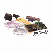
KIT DEV RABBITCORE/RCM3400
Manufacturer
Rabbit Semiconductor
Series
RabbitCore 3000r
Type
MPU Moduler
Datasheet
1.101-0561.pdf
(154 pages)
Specifications of 101-0587
Rohs Status
RoHS non-compliant
Contents
RabbitCore Module, Dev. Board, AC Adapter, Cable and Dynamic C® CD-Rom
Processor To Be Evaluated
RCM3400
Data Bus Width
8 bit
Interface Type
Ethernet
Maximum Operating Temperature
+ 85 C
Minimum Operating Temperature
- 40 C
Operating Supply Voltage
2.8 V to 3.45 V
For Use With/related Products
RCM3400
Lead Free Status / Rohs Status
Lead free / RoHS Compliant
Other names
316-1027


4.4 A/D Converter
The RCM3400 has an onboard ADS7870 A/D converter whose scaling and filtering are
done via the motherboard on which the RCM3400 module is mounted. The A/D converter
multiplexes converted signals from eight single-ended or four differential inputs to Serial
Port B on the Rabbit 3000.
The eight analog input pins, LN0–LN7, each have an input impedance of 6–7 MΩ,
depending on whether they are used as single-ended or differential inputs. The input signal
can range from -2 V to +2 V (differential mode) or from 0 V to +2 V (single-ended mode).
Use a resistor divider such as the one shown in Figure 8 for the analog inputs.
Figure 8. Resistor Divider Network for Analog Inputs
R0 and R1 are typically 20 kΩ to 100 kΩ, with a lower resistance leading to more accu-
racy, but at the expense of a higher current draw. R10 and R11 would then be 180 kΩ to
900 kΩ for a 10:1 attenuator. The capacitor filters noise pulses on the A/D converter input.
The actual voltage range for a signal going to the A/D converter input is also affected by
the 1, 2, 4, 5. 8, 10, 16, and 20 V/V software-programmable gains available on each chan-
nel of the ADS7870 A/D converter. Thus, you must scale the analog signal with an attenu-
ator circuit and a software-programmable gain so that the actual input presented to the
A/D converter is within the range limits of the ADS7870 A/D converter chip (-2 V to + 2 V
or 0 V to + 2 V).
The A/D converter chip can only accept positive voltages. With resistors R0 and R1 con-
nected to ground, your analog circuit is well-suited to perform positive A/D conversions.
When R0 and R1 are tied to ground for differential measurements, both differential inputs
must be referenced to analog ground, and both inputs must be positive with respect to ana-
log ground.
User’s Manual
31
Related parts for 101-0587
Image
Part Number
Description
Manufacturer
Datasheet
Request
R

Part Number:
Description:
COMPUTER SNGLBD BL2101 A/D 0-10V
Manufacturer:
Rabbit Semiconductor
Part Number:
Description:
CARD D/A 0-10V SR9400 SMARTSTAR
Manufacturer:
Rabbit Semiconductor
Datasheet:
Part Number:
Description:
CARD A/D 0-10V SR9300 SMARTSTAR
Manufacturer:
Rabbit Semiconductor
Datasheet:

Part Number:
Description:
WiFi / 802.11 Modules & Development Tools WIRELESS CONTROL APP KIT
Manufacturer:
Rabbit Semiconductor

Part Number:
Description:
KIT DEV RABBITCORE RCM3750
Manufacturer:
Rabbit Semiconductor
Datasheet:
Part Number:
Description:
KIT DEV RABBIT 2000 INT'L
Manufacturer:
Rabbit Semiconductor
Datasheet:
Part Number:
Description:
KIT DEV RABBIT RCM2000 INT'L
Manufacturer:
Rabbit Semiconductor
Datasheet:

Part Number:
Description:
KIT DEVELOPMENT RCM3700 INT'L
Manufacturer:
Rabbit Semiconductor
Datasheet:

Part Number:
Description:
BL4S200 TOOL KIT
Manufacturer:
Rabbit Semiconductor
Datasheet:
Part Number:
Description:
MODULE RABBITCORE RCM3720
Manufacturer:
Rabbit Semiconductor
Datasheet:
Part Number:
Description:
MODULE RABBITCORE RCM3220
Manufacturer:
Rabbit Semiconductor
Datasheet:
Part Number:
Description:
MODULE RABBITCORE RCM3210
Manufacturer:
Rabbit Semiconductor
Datasheet:
Part Number:
Description:
COMPUTER SGL-BOARD OP6600 W/SRAM
Manufacturer:
Rabbit Semiconductor
Datasheet:
Part Number:
Description:
COMPUTER SGL-BD BL2000 SRAM/FLSH
Manufacturer:
Rabbit Semiconductor