101-0587 Rabbit Semiconductor, 101-0587 Datasheet - Page 85
101-0587
Manufacturer Part Number
101-0587
Description
KIT DEV RABBITCORE/RCM3400
Manufacturer
Rabbit Semiconductor
Series
RabbitCore 3000r
Type
MPU Moduler
Datasheet
1.101-0561.pdf
(154 pages)
Specifications of 101-0587
Rohs Status
RoHS non-compliant
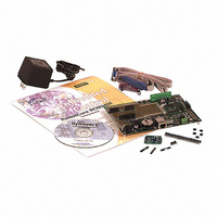
Contents
RabbitCore Module, Dev. Board, AC Adapter, Cable and Dynamic C® CD-Rom
Processor To Be Evaluated
RCM3400
Data Bus Width
8 bit
Interface Type
Ethernet
Maximum Operating Temperature
+ 85 C
Minimum Operating Temperature
- 40 C
Operating Supply Voltage
2.8 V to 3.45 V
For Use With/related Products
RCM3400
Lead Free Status / Rohs Status
Lead free / RoHS Compliant
Other names
316-1027


There is a 2" × 4" through-hole prototyping space available on the Prototyping Board. The
holes in the prototyping area are spaced at 0.1" (2.5 mm). +3.3 V, +5 V, and GND traces run
along the edge of the Prototyping Board for easy access. Small to medium circuits can be
prototyped using point-to-point wiring with 20 to 30 AWG wire between the prototyping
area, the +3.3 V, +5 V, and GND traces, and the surrounding area where surface-mount
components may be installed. Small holes are provided around the surface-mounted com-
ponents that may be installed around the prototyping area.
B.4.1 Adding Other Components
There are two sets of pads for 28-pin devices that can be used for surface-mount prototyp-
ing involving SOIC devices.There are also pads that can be used for SMT resistors and
capacitors in an 0805 SMT package. Each component has every one of its pin pads con-
nected to a hole in which a 30 AWG wire can be soldered (standard wire wrap wire can be
soldered in for point-to-point wiring on the Prototyping Board). Because the traces are
very thin, carefully determine which set of holes is connected to which surface-mount pad.
B.4.2 Measuring Current Draw
The Prototyping Board has a current-measurement feature available on header JP10. Nor-
mally, a jumper connects pins 1–2 and pins 5–6 on header JP10, which provide jumper
connections for the +5 V and the +3.3 V regulated voltages respectively. You may remove
a jumper and place an ammeter across the pins instead, as shown in the example in
Figure B-5, to measure the current being drawn.
Figure B-5. Prototyping Board Current-Measurement Option
User’s Manual
79
Related parts for 101-0587
Image
Part Number
Description
Manufacturer
Datasheet
Request
R

Part Number:
Description:
COMPUTER SNGLBD BL2101 A/D 0-10V
Manufacturer:
Rabbit Semiconductor
Part Number:
Description:
CARD D/A 0-10V SR9400 SMARTSTAR
Manufacturer:
Rabbit Semiconductor
Datasheet:
Part Number:
Description:
CARD A/D 0-10V SR9300 SMARTSTAR
Manufacturer:
Rabbit Semiconductor
Datasheet:

Part Number:
Description:
WiFi / 802.11 Modules & Development Tools WIRELESS CONTROL APP KIT
Manufacturer:
Rabbit Semiconductor

Part Number:
Description:
KIT DEV RABBITCORE RCM3750
Manufacturer:
Rabbit Semiconductor
Datasheet:
Part Number:
Description:
KIT DEV RABBIT 2000 INT'L
Manufacturer:
Rabbit Semiconductor
Datasheet:
Part Number:
Description:
KIT DEV RABBIT RCM2000 INT'L
Manufacturer:
Rabbit Semiconductor
Datasheet:

Part Number:
Description:
KIT DEVELOPMENT RCM3700 INT'L
Manufacturer:
Rabbit Semiconductor
Datasheet:

Part Number:
Description:
BL4S200 TOOL KIT
Manufacturer:
Rabbit Semiconductor
Datasheet:
Part Number:
Description:
MODULE RABBITCORE RCM3720
Manufacturer:
Rabbit Semiconductor
Datasheet:
Part Number:
Description:
MODULE RABBITCORE RCM3220
Manufacturer:
Rabbit Semiconductor
Datasheet:
Part Number:
Description:
MODULE RABBITCORE RCM3210
Manufacturer:
Rabbit Semiconductor
Datasheet:
Part Number:
Description:
COMPUTER SGL-BOARD OP6600 W/SRAM
Manufacturer:
Rabbit Semiconductor
Datasheet:
Part Number:
Description:
COMPUTER SGL-BD BL2000 SRAM/FLSH
Manufacturer:
Rabbit Semiconductor