C8051F064EK Silicon Laboratories Inc, C8051F064EK Datasheet - Page 225
C8051F064EK
Manufacturer Part Number
C8051F064EK
Description
KIT EVAL FOR C8051F064
Manufacturer
Silicon Laboratories Inc
Type
MCUr
Specifications of C8051F064EK
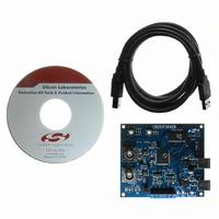
Contents
Evaluation Board, Power Supply, USB Cables, Adapter and Documentation
Processor To Be Evaluated
C8051F06x
Interface Type
USB
Silicon Manufacturer
Silicon Labs
Core Architecture
8051
Silicon Core Number
C8051F064
Silicon Family Name
C8051F06x
Lead Free Status / RoHS Status
Contains lead / RoHS non-compliant
For Use With/related Products
C8051F064
Lead Free Status / Rohs Status
Lead free / RoHS Compliant
Other names
336-1219


C8051F060/1/2/3/4/5/6/7
19.
Controller Area Network (CAN0, C8051F060/1/2/3)
IMPORTANT DOCUMENTATION NOTE: The Bosch CAN Controller is integrated in the C8051F060/1/2/3
devices. This section of the data sheet gives a description of the CAN controller as an overview and offers
a description of how the Silicon Labs CIP-51 MCU interfaces with the on-chip Bosch CAN controller. In
order to use the CAN controller, please refer to Bosch’s C_CAN User’s Manual (revision 1.2) as an accom-
panying manual to Silicon Labs’ C8051F060/1/2/3/4/5/6/7 Data sheet.
The C8051F060/1/2/3 family of devices feature a Control Area Network (CAN) controller that enables
serial communication using the CAN protocol. Silicon Labs CAN controller facilitates communication on a
CAN network in accordance with the Bosch specification 2.0A (basic CAN) and 2.0B (full CAN). The CAN
controller consists of a CAN Core, Message RAM (separate from the CIP-51 RAM), a message handler
state machine, and control registers. Silicon Labs CAN is a protocol controller and does not provide physi-
cal layer drivers (i.e., transceivers). Figure 19.2 shows an example typical configuration on a CAN bus.
Silicon Labs CAN operates at bit rates of up to 1 Mbit/second, though this can be limited by the physical
layer chosen to transmit data on the CAN bus. The CAN processor has 32 Message Objects that can be
configured to transmit or receive data. Incoming data, message objects and their identifier masks are
stored in the CAN message RAM. All protocol functions for transmission of data and acceptance filtering is
performed by the CAN controller and not by the CIP-51 MCU. In this way, minimal CPU bandwidth is
needed to use CAN communication. The CIP-51 configures the CAN controller, accesses received data,
and passes data for transmission via Special Function Registers (SFR) in the CIP-51. The CAN control-
, or CAN_CLK in the C_CAN User’s Guide) is equal to the CIP-51 MCU’s clock (SYSCLK).
ler’s clock (f
sys
Rev. 1.2
225
Related parts for C8051F064EK
Image
Part Number
Description
Manufacturer
Datasheet
Request
R

Part Number:
Description:
SMD/C°/SINGLE-ENDED OUTPUT SILICON OSCILLATOR
Manufacturer:
Silicon Laboratories Inc
Part Number:
Description:
Manufacturer:
Silicon Laboratories Inc
Datasheet:
Part Number:
Description:
N/A N/A/SI4010 AES KEYFOB DEMO WITH LCD RX
Manufacturer:
Silicon Laboratories Inc
Datasheet:
Part Number:
Description:
N/A N/A/SI4010 SIMPLIFIED KEY FOB DEMO WITH LED RX
Manufacturer:
Silicon Laboratories Inc
Datasheet:
Part Number:
Description:
N/A/-40 TO 85 OC/EZLINK MODULE; F930/4432 HIGH BAND (REV E/B1)
Manufacturer:
Silicon Laboratories Inc
Part Number:
Description:
EZLink Module; F930/4432 Low Band (rev e/B1)
Manufacturer:
Silicon Laboratories Inc
Part Number:
Description:
I°/4460 10 DBM RADIO TEST CARD 434 MHZ
Manufacturer:
Silicon Laboratories Inc
Part Number:
Description:
I°/4461 14 DBM RADIO TEST CARD 868 MHZ
Manufacturer:
Silicon Laboratories Inc
Part Number:
Description:
I°/4463 20 DBM RFSWITCH RADIO TEST CARD 460 MHZ
Manufacturer:
Silicon Laboratories Inc
Part Number:
Description:
I°/4463 20 DBM RADIO TEST CARD 868 MHZ
Manufacturer:
Silicon Laboratories Inc
Part Number:
Description:
I°/4463 27 DBM RADIO TEST CARD 868 MHZ
Manufacturer:
Silicon Laboratories Inc
Part Number:
Description:
I°/4463 SKYWORKS 30 DBM RADIO TEST CARD 915 MHZ
Manufacturer:
Silicon Laboratories Inc
Part Number:
Description:
N/A N/A/-40 TO 85 OC/4463 RFMD 30 DBM RADIO TEST CARD 915 MHZ
Manufacturer:
Silicon Laboratories Inc
Part Number:
Description:
I°/4463 20 DBM RADIO TEST CARD 169 MHZ
Manufacturer:
Silicon Laboratories Inc