MPC8313E-RDBB Freescale Semiconductor, MPC8313E-RDBB Datasheet - Page 19
MPC8313E-RDBB
Manufacturer Part Number
MPC8313E-RDBB
Description
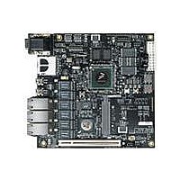
BOARD CPU 8313E VER 2.1
Manufacturer
Freescale Semiconductor
Series
PowerQUICC II™ PROr
Type
MPUr
Datasheets
1.MPC8313CZQAFFB.pdf
(100 pages)
2.MPC8313E-RDBB.pdf
(52 pages)
3.MPC8313E-RDBB.pdf
(2 pages)
Specifications of MPC8313E-RDBB
Contents
Board
Processor To Be Evaluated
MPC8xxx
Data Bus Width
32 bit
Interface Type
Ethernet, USB, JTAG, SPI, UART
Dimensions
170 mm x 170 mm
Operating Supply Voltage
3.3 V
For Use With/related Products
MPC8313E
Lead Free Status / RoHS Status
Lead free / RoHS Compliant


2.13
The common on-chip processor (COP) is part of the MPC8313E JTAG module and is implemented as a
set of additional instructions and logic. This port can connect to a dedicated emulator for extensive system
debugging. Several third-party emulators in the market can connect to the host computer through the
Ethernet port, USB port, parallel port, RS-232, and so on. A typical setup using a USB port emulator is
shown in
The 16-pin generic header connector carries the COP/JTAG signals and the additional signals for system
debugging. The pinout of this connector is shown in
3
Table 3
the number of the section/page on which each is discussed. The rest of this section discusses each of these
in the order of its appearance in the table.
Freescale Semiconductor
Reference
P1
Connectors, Jumpers, Switches, and LEDs
summarizes the connectors, jumpers, switches, and LEDs on the MPC8313E RDB and provides
Figure
COP/JTAG Port
14-pin COP/JTAG connector
18.
PC
PowerQUICC™ MPC8313E Reference Design Board (RDB), Rev. 4
Figure 18. Connecting MPC8313E-RDB to a USB Emulator
Table 3. Connectors, Jumpers, Switches, and LEDs
USB Port
Figure 19. MPC8313E RDB COP Connector
CKSTP_OUT
HRESET
SRESET
Pull-up
TMS
TCK
TDO
TDI
Connectors
Description
1
Figure
GND
TRST
Pull-up
CKSTP_IN
NC
NC
NC
GND
19.
Emulator
USB
Connectors, Jumpers, Switches, and LEDs
P1
COP Port
MPC8313E RDB
Section/Page
3.1/Page 21
19
Related parts for MPC8313E-RDBB
Image
Part Number
Description
Manufacturer
Datasheet
Request
R

Part Number:
Description:
Mpc8313e Powerquicc Ii Pro Processor
Manufacturer:
Freescale Semiconductor, Inc
Datasheet:

Part Number:
Description:
BOARD PROCESSOR
Manufacturer:
Freescale Semiconductor
Datasheet:

Part Number:
Description:
BOARD CPU 8313E VER 2.2
Manufacturer:
Freescale Semiconductor
Datasheet:
Part Number:
Description:
Microprocessors - MPU 8313 REV2.2 PB ENC EXT
Manufacturer:
Freescale Semiconductor
Datasheet:
Part Number:
Description:
Microprocessors - MPU 8313 REV2.2 PB W/ENC
Manufacturer:
Freescale Semiconductor
Datasheet:
Part Number:
Description:
Microprocessors - MPU 8313 REV2.2 PB NO EN EXT
Manufacturer:
Freescale Semiconductor
Datasheet:
Part Number:
Description:
Microprocessors - MPU 8313 REV2.2 PB NO ENC
Manufacturer:
Freescale Semiconductor
Datasheet:
Part Number:
Description:
Manufacturer:
Freescale Semiconductor, Inc
Datasheet:
Part Number:
Description:
Manufacturer:
Freescale Semiconductor, Inc
Datasheet:
Part Number:
Description:
Manufacturer:
Freescale Semiconductor, Inc
Datasheet:
Part Number:
Description:
Manufacturer:
Freescale Semiconductor, Inc
Datasheet:
Part Number:
Description:
Manufacturer:
Freescale Semiconductor, Inc
Datasheet:
Part Number:
Description:
Manufacturer:
Freescale Semiconductor, Inc
Datasheet:
Part Number:
Description:
Manufacturer:
Freescale Semiconductor, Inc
Datasheet:
Part Number:
Description:
Manufacturer:
Freescale Semiconductor, Inc
Datasheet: