MPC8313E-RDBB Freescale Semiconductor, MPC8313E-RDBB Datasheet - Page 20
MPC8313E-RDBB
Manufacturer Part Number
MPC8313E-RDBB
Description
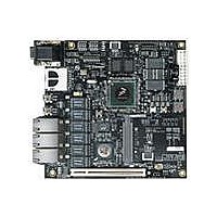
BOARD CPU 8313E VER 2.1
Manufacturer
Freescale Semiconductor
Series
PowerQUICC II™ PROr
Type
MPUr
Datasheets
1.MPC8313CZQAFFB.pdf
(100 pages)
2.MPC8313E-RDBB.pdf
(52 pages)
3.MPC8313E-RDBB.pdf
(2 pages)
Specifications of MPC8313E-RDBB
Contents
Board
Processor To Be Evaluated
MPC8xxx
Data Bus Width
32 bit
Interface Type
Ethernet, USB, JTAG, SPI, UART
Dimensions
170 mm x 170 mm
Operating Supply Voltage
3.3 V
For Use With/related Products
MPC8313E
Lead Free Status / RoHS Status
Lead free / RoHS Compliant


Connectors, Jumpers, Switches, and LEDs
20
Reference
P10
P11
U44
BT1
D12
D10
J20
J21
J22
J23
J24
J19
P2
P3
P4
P5
P6
P7
P8
P9
S1
S2
S3
S4
D6
D7
D8
D9
3.3 V PCI Slot [IDSEL - AD15]
MiniPCI Slot [IDSEL - AD14]
USB mini-AB Connector (on-chip PHY)
RJ-45 LAN connectors Enet4 (top), Enet5 (bottom). See
RJ-45 LAN connectors Enet2 (top), Enet3 (bottom). See
RJ-45 LAN connectors Enet0 (top), Enet1 (bottom). See
USB mini-AB Connector (external ULPI USB PHY)
ATX type power supply connector. The board can be powered by an ATX power supply or
the power supply bundled with the mini-ITX case.
IEEE 1588 connector (Optional)
Dual UART connector. UART1 (top), UART2 (bottom)
SD memory card socket
RTC battery holder, CR2032 type. The real-time clock on the RDB requires a battery when
the board is powered off. When placing or replacing the battery, take care to ensure that the
polarity is correct.
Connector for chassis connection (power on, power LED, reset)
LCD connector
LCD connector
LCD backlight connector. A 2-pin header (J23) is provided for LCD backlight power. Pin1 is
5 V and pin 2 is GND.
MCU programming connector. J24 is used for MCU programming on the RDB. It is reserved.
Open (Default)—Power ON controlled by switch; Close—Power is always ON
System reset button. Resets the MPC8313E RDB. (PORESET). Press once on the push
button reset switch on the RDB to cause a power-on reset (PORESET) to the board.
Power ON button. Press once to power ON/OFF.
DIP switch. Selects the reset configuration source (RST_CFG_SRC) for the MPC8313E.
DIP switch. Board revision indicator and boot device selector.
Enet5 Link 10
Enet5 Link 100
Enet5 Duplex
Enet5 RX
USB VBUS
On-chip USB PHY CTL0
Table 3. Connectors, Jumpers, Switches, and LEDs (continued)
PowerQUICC™ MPC8313E Reference Design Board (RDB), Rev. 4
Description
Switches
Jumpers
LEDs
Figure 23
Figure 23
Figure 23
Freescale Semiconductor
Section/Page
3.10/Page 26
3.11/Page 26
3.2/Page 21
3.3/Page 22
3.4/Page 22
3.5/Page 23
3.4/Page 22
3.9/Page 25
3.6/Page 24
3.7/Page 24
3.8/Page 24
—
—
—
—
—
—
—
—
—
—
—
—
—
—
Related parts for MPC8313E-RDBB
Image
Part Number
Description
Manufacturer
Datasheet
Request
R

Part Number:
Description:
Mpc8313e Powerquicc Ii Pro Processor
Manufacturer:
Freescale Semiconductor, Inc
Datasheet:

Part Number:
Description:
BOARD PROCESSOR
Manufacturer:
Freescale Semiconductor
Datasheet:

Part Number:
Description:
BOARD CPU 8313E VER 2.2
Manufacturer:
Freescale Semiconductor
Datasheet:
Part Number:
Description:
Microprocessors - MPU 8313 REV2.2 PB ENC EXT
Manufacturer:
Freescale Semiconductor
Datasheet:
Part Number:
Description:
Microprocessors - MPU 8313 REV2.2 PB W/ENC
Manufacturer:
Freescale Semiconductor
Datasheet:
Part Number:
Description:
Microprocessors - MPU 8313 REV2.2 PB NO EN EXT
Manufacturer:
Freescale Semiconductor
Datasheet:
Part Number:
Description:
Microprocessors - MPU 8313 REV2.2 PB NO ENC
Manufacturer:
Freescale Semiconductor
Datasheet:
Part Number:
Description:
Manufacturer:
Freescale Semiconductor, Inc
Datasheet:
Part Number:
Description:
Manufacturer:
Freescale Semiconductor, Inc
Datasheet:
Part Number:
Description:
Manufacturer:
Freescale Semiconductor, Inc
Datasheet:
Part Number:
Description:
Manufacturer:
Freescale Semiconductor, Inc
Datasheet:
Part Number:
Description:
Manufacturer:
Freescale Semiconductor, Inc
Datasheet:
Part Number:
Description:
Manufacturer:
Freescale Semiconductor, Inc
Datasheet:
Part Number:
Description:
Manufacturer:
Freescale Semiconductor, Inc
Datasheet:
Part Number:
Description:
Manufacturer:
Freescale Semiconductor, Inc
Datasheet: