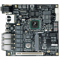
MPC8313E-RDB Freescale Semiconductor, MPC8313E-RDB Datasheet - Page 43

MPC8313E-RDB
Manufacturer Part Number
MPC8313E-RDB
Description
BOARD PROCESSOR
Manufacturer
Freescale Semiconductor
Series
PowerQUICC II™ PROr
Type
MCUr
Datasheets
1.MPC8313CZQAFFB.pdf
(100 pages)
2.MPC8313E-RDBB.pdf
(52 pages)
3.MPC8313E-RDBB.pdf
(2 pages)
Specifications of MPC8313E-RDB
Contents
Reference Design Board, Software and Documentation
Termination Type
SMD
Supply Voltage Max
1.05V
Tool / Board Applications
Wired Connectivity-LIN, CAN, Ethernet, USB
Mcu Supported Families
POWERQUICC II PRO
Rohs Compliant
Yes
Filter Terminals
SMD
Silicon Manufacturer
Freescale
Silicon Core Number
MPC83xx
Kit Application Type
Communication & Networking
Application Sub Type
Ethernet
Core Architecture
Power Architecture
Silicon Family Name
PowerQUICC II PRO
For Use With/related Products
MPC8313E
Lead Free Status / RoHS Status
Lead free / RoHS Compliant
5.4
Table 22
6
This section describes how to boot the MPC8313E RDB. The on-board flash memory is preloaded with a
flash image from the factory. Before powering up the board, verify that all the on-board DIP switches and
jumpers are set to the factory defaults according to the settings listed in
Settings,”
Freescale Semiconductor
0x0000_0000–0x07FF_FFFF
0x8000_0000–0x9FFF_FFFF
0xE000_0000–0xE00F_FFFF
0xE200_0000–0xE20F_FFFF
0xE280_0000–0xE280_7FFF
0xF000_0000–0xF001_FFFF
0xFA00_0000–0xFA00_7FFF
0xFE00_0000–0xFE7F_FFFF
Voltage
12 V
Address Range
Getting Started
5 V
shows an example memory map on the MPC8313E RDB for U-Boot in NOR Flash memory.
Chip-Select Assignments and Memory Map
Table 22. Example Memory Map, Local Access Window, and Chip-Select Assignments
and make all external connections as described in
Avoid touching areas of integrated circuitry and connectors; static discharge
can damage circuits.
Only the 3.3-V PCI Card is supported. Turn OFF power during insertion and
removal of a PCI card.
Switching power, PCI cards
PowerQUICC™ MPC8313E Reference Design Board (RDB), Rev. 4
DDR2
PCI
Internal bus
PCI
NAND Controller LCS1#
Local bus
Local bus
Local bus
Usage
Target Interface
None
Table 21. Power Supply Usage Summary
MCS0#
Nil
Nil
Nil
LCS2#
LCS3#
LCS0#
Chip-Select
WARNING
CAUTION
Line
Budget
0.5–1 A
Nil
DDR SDRAM (128 Mbyte)
PCI memory space (512 Mbyte)
IMMR (1 Mbyte)
PCI I/O space (1 Mbyte)
NAND Flash window (32Kbyte)
VSC7385 (128Kbyte)
Read/write buffer (32Kbyte)
Boot Flash (8 Mbyte)
Section 6.2, “External Cable Connections.”
Device Name
Section 6.1, “Board Jumper
Direct from ATX Power
Direct from ATX Power
Solution
32
32
—
32
8
8
8
16
Port Size (Bits)
Getting Started
43


