MPC8313E-RDB Freescale Semiconductor, MPC8313E-RDB Datasheet - Page 49
MPC8313E-RDB
Manufacturer Part Number
MPC8313E-RDB
Description
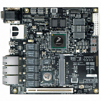
BOARD PROCESSOR
Manufacturer
Freescale Semiconductor
Series
PowerQUICC II™ PROr
Type
MCUr
Datasheets
1.MPC8313CZQAFFB.pdf
(100 pages)
2.MPC8313E-RDBB.pdf
(52 pages)
3.MPC8313E-RDBB.pdf
(2 pages)
Specifications of MPC8313E-RDB
Contents
Reference Design Board, Software and Documentation
Termination Type
SMD
Supply Voltage Max
1.05V
Tool / Board Applications
Wired Connectivity-LIN, CAN, Ethernet, USB
Mcu Supported Families
POWERQUICC II PRO
Rohs Compliant
Yes
Filter Terminals
SMD
Silicon Manufacturer
Freescale
Silicon Core Number
MPC83xx
Kit Application Type
Communication & Networking
Application Sub Type
Ethernet
Core Architecture
Power Architecture
Silicon Family Name
PowerQUICC II PRO
For Use With/related Products
MPC8313E
Lead Free Status / RoHS Status
Lead free / RoHS Compliant


8.3
Set DIP switch S4 as OFF-OFF-OFF-ON (1110) and set DIP switch S3 as ON-ON-ON-OFF (0001). Note
that there is no boot image on NAND flash memory with the default shipment.
8.4
Some ATX power supplies may need a large 5-V loading to stabilize the 3.3-V output; otherwise, you may
observe the 3.3 V lowered to around 2.9 V–3 V. The consequence can be a periodic reset by the on-board
voltage monitoring circuit. For a workaround, you may take one of the following actions:
Starting from revision REVA2, a resistor loading for 5 V is added. It should work better with the ATX
power supply that requires large 5-V loading. If there is still a problem, simply apply one of the
workarounds presented here.
8.5
The PMC registers range from IMMR + 0x0B00 to IMMR + 0x0BFF. When this area is accessed in u-boot,
the RDB hangs up. It appears that the PMC block is related to the JTAG interface; TRST must not be pulled
down for normal operation of the PMC block. Possible workarounds are as follows:
9
Table 25
Freescale Semiconductor
•
•
•
•
•
•
Number
Rev.
0
1
2
Add a 5-V loading to the power supply, for example, attach a hard disk drive.
Change to another ATX power supply that does not require a large 5-V loading.
Use the power supply provided with the RDB package.
Attach a debugger to drive TRST high during normal operation.
Remove the pull-down resistor (R37) for TRST. Although this tested on some RDBs without any
problem, it violates the hardware specification. If it does not work on your RDB, use another
workaround.
This problem is fixed in REVA3
Revision History
provides a revision history for this document.
What is the hardware setting for boot from NAND Flash?
Some ATX power supplies do not work with the RDB?
Power management control (PMC) registers cannot be
accessed?
2/2007
4/2007
4/2007
Date
PowerQUICC™ MPC8313E Reference Design Board (RDB), Rev. 4
Initial public release.
Replaced a faulty table of contents and restructured sections of the document for clarity.
Added information to Section 8, Frequently Asked Questions (FAQs)
Table 25. Document Revision History
Substantive Change(s)
Revision History
49
Related parts for MPC8313E-RDB
Image
Part Number
Description
Manufacturer
Datasheet
Request
R

Part Number:
Description:
Mpc8313e Powerquicc Ii Pro Processor
Manufacturer:
Freescale Semiconductor, Inc
Datasheet:

Part Number:
Description:
BOARD CPU 8313E VER 2.1
Manufacturer:
Freescale Semiconductor
Datasheet:

Part Number:
Description:
BOARD CPU 8313E VER 2.2
Manufacturer:
Freescale Semiconductor
Datasheet:
Part Number:
Description:
Microprocessors - MPU 8313 REV2.2 PB ENC EXT
Manufacturer:
Freescale Semiconductor
Datasheet:
Part Number:
Description:
Microprocessors - MPU 8313 REV2.2 PB W/ENC
Manufacturer:
Freescale Semiconductor
Datasheet:
Part Number:
Description:
Microprocessors - MPU 8313 REV2.2 PB NO EN EXT
Manufacturer:
Freescale Semiconductor
Datasheet:
Part Number:
Description:
Microprocessors - MPU 8313 REV2.2 PB NO ENC
Manufacturer:
Freescale Semiconductor
Datasheet:
Part Number:
Description:
Manufacturer:
Freescale Semiconductor, Inc
Datasheet:
Part Number:
Description:
Manufacturer:
Freescale Semiconductor, Inc
Datasheet:
Part Number:
Description:
Manufacturer:
Freescale Semiconductor, Inc
Datasheet:
Part Number:
Description:
Manufacturer:
Freescale Semiconductor, Inc
Datasheet:
Part Number:
Description:
Manufacturer:
Freescale Semiconductor, Inc
Datasheet:
Part Number:
Description:
Manufacturer:
Freescale Semiconductor, Inc
Datasheet:
Part Number:
Description:
Manufacturer:
Freescale Semiconductor, Inc
Datasheet:
Part Number:
Description:
Manufacturer:
Freescale Semiconductor, Inc
Datasheet: