DEMO9RS08KB12 Freescale Semiconductor, DEMO9RS08KB12 Datasheet - Page 12
DEMO9RS08KB12
Manufacturer Part Number
DEMO9RS08KB12
Description
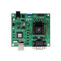
DEMO BOARD FOR 9RS08KA12
Manufacturer
Freescale Semiconductor
Series
RS08r
Type
MCUr
Datasheets
1.DEMO9RS08KB12.pdf
(13 pages)
2.DEMO9RS08KB12.pdf
(48 pages)
3.DEMO9RS08KB12.pdf
(8 pages)
Specifications of DEMO9RS08KB12
Design Resources
DEMO9RS08KB12 Schematic
Contents
Board, Cable, DVD and Guide
Processor To Be Evaluated
RS08
Data Bus Width
8 bit, 10 bit
Operating Supply Voltage
- 0.3 V to + 5.8 V
Tool Type
Demonstration Board
Core Architecture
68RS08
Cpu Core
RS08
Silicon Manufacturer
Freescale
Core Sub-architecture
RS08
Silicon Core Number
MC9RS08
Silicon Family Name
RS08KB
Rohs Compliant
Yes
For Use With/related Products
MC9RS08KB12
Lead Free Status / RoHS Status
Lead free / RoHS Compliant


D E M O 9 S 0 8 K B 1 2
N O V E M B E R
1 6 ,
2 0 0 9
U S E R
G U I D E
USER OPTIONS
The DEMO9RS08KB12 includes various input and output devices to aid application
development and debug. User I/O includes 2 momentary pushbutton switches, 2 green LEDs,
1 potentiometer, 1 Light Sensor. Each device may be enabled or disabled individually with the
USER_EN option header. Each user enable is clearly marked as to functionality.
Pushbutton Switches
Two push button switches provide momentary, active-low input, for user applications. External pull-
ups internal bias the switches for proper operation. Pushbutton switches SW1 and SW2 are
enabled to the MCU I/O ports by the USER_EN option bank. Figure 8 below shows the jumper
setting for the pushbutton switches.
LED Indicators
Two LEDs provide visual output for user applications. Both LEDs are configured for active-low
operation. Figure 8 below shows the jumper setting for the LED’s.
Potentiometer
A 5k ohm, thumb-wheel type, potentiometer at RV1 provides variable resistance input for user
applications. The output is the result of a voltage divider that changes as the thumb-wheel is
turned. The potentiometer is connected between VDD and GND with the center tap providing the
divider output. Figure 8 below shows the jumper setting for the POT.
Light Sensor
A surface-mount phototransistor, at RZ1, provides light sensitive, variable input for user
applications. Current flow within the phototransistor is inversely proportional to light intensity
incident on the surface of the device. A rail-to-rail OP amp at U5 boosts the photocell output to
useable levels. Figure 8 below shows the jumper setting for the Light Sensor.
12
Related parts for DEMO9RS08KB12
Image
Part Number
Description
Manufacturer
Datasheet
Request
R

Part Number:
Description:
Manufacturer:
Freescale Semiconductor, Inc
Datasheet:
Part Number:
Description:
Manufacturer:
Freescale Semiconductor, Inc
Datasheet:
Part Number:
Description:
Manufacturer:
Freescale Semiconductor, Inc
Datasheet:
Part Number:
Description:
Manufacturer:
Freescale Semiconductor, Inc
Datasheet:
Part Number:
Description:
Manufacturer:
Freescale Semiconductor, Inc
Datasheet:
Part Number:
Description:
Manufacturer:
Freescale Semiconductor, Inc
Datasheet:
Part Number:
Description:
Manufacturer:
Freescale Semiconductor, Inc
Datasheet:
Part Number:
Description:
Manufacturer:
Freescale Semiconductor, Inc
Datasheet:
Part Number:
Description:
Manufacturer:
Freescale Semiconductor, Inc
Datasheet:
Part Number:
Description:
Manufacturer:
Freescale Semiconductor, Inc
Datasheet:
Part Number:
Description:
Manufacturer:
Freescale Semiconductor, Inc
Datasheet:
Part Number:
Description:
Manufacturer:
Freescale Semiconductor, Inc
Datasheet:
Part Number:
Description:
Manufacturer:
Freescale Semiconductor, Inc
Datasheet:
Part Number:
Description:
Manufacturer:
Freescale Semiconductor, Inc
Datasheet:
Part Number:
Description:
Manufacturer:
Freescale Semiconductor, Inc
Datasheet: