DEMO9RS08KB12 Freescale Semiconductor, DEMO9RS08KB12 Datasheet - Page 7
DEMO9RS08KB12
Manufacturer Part Number
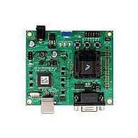
DEMO9RS08KB12
Description
DEMO BOARD FOR 9RS08KA12
Manufacturer
Freescale Semiconductor
Series
RS08r
Type
MCUr
Datasheets
1.DEMO9RS08KB12.pdf
(13 pages)
2.DEMO9RS08KB12.pdf
(48 pages)
3.DEMO9RS08KB12.pdf
(8 pages)
Specifications of DEMO9RS08KB12
Design Resources
DEMO9RS08KB12 Schematic
Contents
Board, Cable, DVD and Guide
Processor To Be Evaluated
RS08
Data Bus Width
8 bit, 10 bit
Operating Supply Voltage
- 0.3 V to + 5.8 V
Tool Type
Demonstration Board
Core Architecture
68RS08
Cpu Core
RS08
Silicon Manufacturer
Freescale
Core Sub-architecture
RS08
Silicon Core Number
MC9RS08
Silicon Family Name
RS08KB
Rohs Compliant
Yes
For Use With/related Products
MC9RS08KB12
Lead Free Status / RoHS Status
Lead free / RoHS Compliant


U S E R
SOFTWARE DEVELOPMENT
Software development requires the use of a compiler or an assembler supporting the HCS08
instruction set and a host PC operating a debug interface. CodeWarrior Development Studio
for Microcontrollers is supplied with this board for application development and debug. Refer
to the supporting CodeWarrior documentation for details on use and capabilities.
DEVELOPMENT SUPPORT
Application development and debug for the target MC9RS08KB12 is supported through the
integrated Background Debug Mode (BDM) interface. An optional 6-pos BDM_PORT header
allows connecting an external HCS12/HCS08 BDM cable. The BDM_PORT header is not
installed in default configurations.
Integrated BDM
The DEMO9RS08KB12 board features an integrated BDM.
supports application development and debugging via background debug mode. The integrated
BDM is fully supported by CodeWarrior development tools.
The integrated USB BDM provides power and ground to the target board eliminating the need
to power the board externally. Power from the USB BDM is derived from the USB bus. The
integrated USB BDM is designed to sink a maximum of 300mA of current from the USB bus.
Therefore, total current consumption for the target board, and connected circuitry, must not
exceed 300mA. This current limit describes the current supplied by the USB cable to the
BDM circuit, the target board, and any connected circuitry. Excessive current drain will violate
the USB specification causing the bus to disconnect. Damage to the host PC USB hub or the
target board may result.
BDM_PORT Header
A compatible HCS12 BDM cable may also attach to the 6-pin BDM interface header
(BDM_PORT). Figure 2 below shows the pin-out for the BDM_PORT header.
Figure 2: BDM_PORT Header
G U I D E
NOTE: The BDM_PORT header is not installed in default configuration.
BKGD 1
3
5
2 GND
4 RESET*
6 VDD
See the MC9RS08KB12 Reference Manual for details
7
The integrated USB BDM
Related parts for DEMO9RS08KB12
Image
Part Number
Description
Manufacturer
Datasheet
Request
R

Part Number:
Description:
Manufacturer:
Freescale Semiconductor, Inc
Datasheet:
Part Number:
Description:
Manufacturer:
Freescale Semiconductor, Inc
Datasheet:
Part Number:
Description:
Manufacturer:
Freescale Semiconductor, Inc
Datasheet:
Part Number:
Description:
Manufacturer:
Freescale Semiconductor, Inc
Datasheet:
Part Number:
Description:
Manufacturer:
Freescale Semiconductor, Inc
Datasheet:
Part Number:
Description:
Manufacturer:
Freescale Semiconductor, Inc
Datasheet:
Part Number:
Description:
Manufacturer:
Freescale Semiconductor, Inc
Datasheet:
Part Number:
Description:
Manufacturer:
Freescale Semiconductor, Inc
Datasheet:
Part Number:
Description:
Manufacturer:
Freescale Semiconductor, Inc
Datasheet:
Part Number:
Description:
Manufacturer:
Freescale Semiconductor, Inc
Datasheet:
Part Number:
Description:
Manufacturer:
Freescale Semiconductor, Inc
Datasheet:
Part Number:
Description:
Manufacturer:
Freescale Semiconductor, Inc
Datasheet:
Part Number:
Description:
Manufacturer:
Freescale Semiconductor, Inc
Datasheet:
Part Number:
Description:
Manufacturer:
Freescale Semiconductor, Inc
Datasheet:
Part Number:
Description:
Manufacturer:
Freescale Semiconductor, Inc
Datasheet: