DEMO9RS08KB12 Freescale Semiconductor, DEMO9RS08KB12 Datasheet - Page 9
DEMO9RS08KB12
Manufacturer Part Number
DEMO9RS08KB12
Description
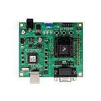
DEMO BOARD FOR 9RS08KA12
Manufacturer
Freescale Semiconductor
Series
RS08r
Type
MCUr
Datasheets
1.DEMO9RS08KB12.pdf
(13 pages)
2.DEMO9RS08KB12.pdf
(48 pages)
3.DEMO9RS08KB12.pdf
(8 pages)
Specifications of DEMO9RS08KB12
Design Resources
DEMO9RS08KB12 Schematic
Contents
Board, Cable, DVD and Guide
Processor To Be Evaluated
RS08
Data Bus Width
8 bit, 10 bit
Operating Supply Voltage
- 0.3 V to + 5.8 V
Tool Type
Demonstration Board
Core Architecture
68RS08
Cpu Core
RS08
Silicon Manufacturer
Freescale
Core Sub-architecture
RS08
Silicon Core Number
MC9RS08
Silicon Family Name
RS08KB
Rohs Compliant
Yes
For Use With/related Products
MC9RS08KB12
Lead Free Status / RoHS Status
Lead free / RoHS Compliant


D E M O 9 S 0 8 K B 1 2
U S E R
Power from the integrated BDM is drawn from the USB bus and is limited to 300 mA. This
current limit accounts for the total current supplied over the USB cable to the BDM circuit, the
target board, and any connected circuitry. Current drain in excess of value violates the USB
specification and will cause the USB bus to disconnect. This will cause the board to exhibit
power cycling where the board appears to turn off and back on continually. Damage to the
host PC or the target board may result.
Voltage input to the on-board regulator should be kept at or below +12V to prevent the
regulator from over heating.
VX_EN
The VX_EN option header is a 2-pin jumper that connects or disconnects input J1-1 directly to
the target board voltage rail. J1-3 connects directly to the target board ground plane. Use of
this feature requires a regulated input power source.
minimize noise but is not regulated or protected. Care should be exercised when using this
feature; no protection is applied on this input and damage to the target board may result if
excessive voltage is applied. Also, do not attempt to power the target board through this
connector while also applying power through the USB BDM or the PWR connector; damage to
the board may result.
Power may also be sourced to off-board circuitry through the J1 connector. The current
supplied from the USB bus or the on-board regulator limits current available to external
circuitry. Excessive current drain may damage the target board, the host PC USB hub, or the
on-board regulator. The figure below details the VX_EN header connections.
Figure 4: VX_EN Option Header
G U I D E
VX_EN
powered from the integrated USB BDM. Damage to the target board or
1
Do not exceed available current from USB-BDM or on-board regulator
Do not configure the target board to draw more than 300mA when
when sourcing power through connector J1 to external circuitry.
2
Enabled
ON
Disabled
OFF
host PC may result otherwise.
CAUTION:
CAUTION:
9
This power input is decoupled to
N O V E M B E R
1 6 ,
2 0 0 9
Related parts for DEMO9RS08KB12
Image
Part Number
Description
Manufacturer
Datasheet
Request
R

Part Number:
Description:
Manufacturer:
Freescale Semiconductor, Inc
Datasheet:
Part Number:
Description:
Manufacturer:
Freescale Semiconductor, Inc
Datasheet:
Part Number:
Description:
Manufacturer:
Freescale Semiconductor, Inc
Datasheet:
Part Number:
Description:
Manufacturer:
Freescale Semiconductor, Inc
Datasheet:
Part Number:
Description:
Manufacturer:
Freescale Semiconductor, Inc
Datasheet:
Part Number:
Description:
Manufacturer:
Freescale Semiconductor, Inc
Datasheet:
Part Number:
Description:
Manufacturer:
Freescale Semiconductor, Inc
Datasheet:
Part Number:
Description:
Manufacturer:
Freescale Semiconductor, Inc
Datasheet:
Part Number:
Description:
Manufacturer:
Freescale Semiconductor, Inc
Datasheet:
Part Number:
Description:
Manufacturer:
Freescale Semiconductor, Inc
Datasheet:
Part Number:
Description:
Manufacturer:
Freescale Semiconductor, Inc
Datasheet:
Part Number:
Description:
Manufacturer:
Freescale Semiconductor, Inc
Datasheet:
Part Number:
Description:
Manufacturer:
Freescale Semiconductor, Inc
Datasheet:
Part Number:
Description:
Manufacturer:
Freescale Semiconductor, Inc
Datasheet:
Part Number:
Description:
Manufacturer:
Freescale Semiconductor, Inc
Datasheet: