YRDKSH7216 Renesas Electronics America, YRDKSH7216 Datasheet
YRDKSH7216
Specifications of YRDKSH7216


Related parts for YRDKSH7216


YRDKSH7216 Summary of contents
Page 1
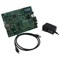
REU10B0007-0100 Renesas Demo Kit (RDK) for SH2A-7216 Rev.1.01 ...
Page 2
By using this Renesas Demo Kit (RDK), the user accepts the following terms. The RDK is not guaranteed to be error free, and the User assumes the entire risk as to the results and performance of the RDK. The ...
Page 3
Table of Contents Chapter 1. Preface ........................................................................................................................ 1 Chapter 2. Purpose ....................................................................................................................... 2 Chapter 3. Power Supply .............................................................................................................. 4 3.1. Requirements................................................................................................................. 4 3.2. Power – Up Behavior ..................................................................................................... 4 3.3. World Wide Kits.............................................................................................................. 4 Chapter 4. Board Layout ............................................................................................................... ...
Page 4
Memory Map .............................................................................................................. 24 Chapter 11. Component Placement............................................................................................ 25 Chapter 12. Additional Information.............................................................................................. 26 12.1. Hardware Partner Information.................................................................................... 26 12.2. Renesas Contact Information..................................................................................... 31 iv ...
Page 5
Cautions This document may be, wholly or partially, subject to change without notice. All rights reserved. The RDK design, documentation, and demo software are intended to improve understanding and time-to-market for SH7216-based designs. Duplication of the design, documentation, and demonstration ...
Page 6
This RDK is an evaluation and demonstration tool for Renesas SH2A and SH2A/7216 microcontrollers. The goal is to provide the user with a powerful debug and demonstration platform targeted at common applications. A set of human/machine interfaces are tightly integrated ...
Page 7
The Renesas RDK user experience is complemented by the online Renesas ecosystem: • Renesas Interactive: o Free Online Learning o User submitted training classes available • Renesas Rulz: www.RenesasRulz.com o Online community o Online user forums www.RenesasRules.com/rdk7216 o • University ...
Page 8
... LED will step through all colors, and the LCD displays the target and measured motor control frequency. 3.3. World Wide Kits The YRDKSH7216W is designed for worldwide operation. The RDK uses a universal input power supply with adapters to accommodate the majority of countries. ...
Page 9
Component Layout The following diagram shows top layer component layout of the board. Reset RST USB Port I/F Ethernet Port Ethernet USB Port CAN (Not Loaded Circuit (NL) SW5 SW1 ...
Page 10
Board Dimensions The following diagram gives the board dimensions and connector positions. All through hole connectors are on a common 0.1” grid for easy interfacing. Figure 4-2: Board Dimensions 6 ...
Page 11
Figure 5-1 shows the CPU board components and their connectivity. Extension Headers RCAN R8-232 Debug LCD Ethernet USB MicroSD Card 3-D Accelerometer EEPROM Chapter 5. Block Diagram Power Jack SH7216 Boot mode pins ADC Timer Mic Speaker Volume Figure 5-1: ...
Page 12
Figure 5-2 shows host PC connection to the RDK board. USB Cable (Not Loaded) Reset Function Headers JN5 RST E10A Debugger Circuitry USB I/F Ethernet Port Ethernet PHY USB Port SH7216 USB CAN CAN Circuit (NL) SW5 SW1 SW3 JN6 ...
Page 13
Switches There are four switches located on the CPU board. The function of each switch and its connection are shown in Table 6-1. Switch SW1 Mode/Debug Switch – Refer to Table 7-1 for details SW2 (RESET) When pressed, the ...
Page 14
Table 6-2 shows the pin allocation and signal names used on this connector. Pin Circuit Net Name 1 Ground 3 No Connection 5 R/W (Wired to Write only Connection 9 No Connection 11 DLCDD4 (PE0) 13 DLCDD6 (PE2) ...
Page 15
LED Reference (As shown on silkscreen) LED1 (Up) LED2 (Un) LED3 (Vp) LED4 (Vn) LED5 (Wp) LED6 (Wn) LED7 (Up’) LED8 (Un’) LED9 (Vp’) LED10 (Vn’) LED11 (Wp’) LED12 (Wn’) LED13 (1PPS ENET) LED14 (Speed ENET) LED15 (E10A DBG) LED16 ...
Page 16
Note: The potentiometer is fitted to offer an easy way of supplying a variable analogue input to the controller. It does not necessarily reflect the accuracy of the controllers ADC. Please see the device manual for details. 6.7. Serial port ...
Page 17
Description VBUS USD+ USD- DRVcc DRVss PUPD USBXTAL USBEXTAL 6.10. Ethernet The Ethernet module conforms to the Ethernet or IEEE802.3 media access control (MAC) standard. Ethernet controller is connected to the direct memory access controller for Ethernet controller (E-DMAC) and ...
Page 18
Table 6-7 contains details of the signal descriptions and pin connections. All connections to the MCU are direct. The National Semiconductor 10/100 DP83640 Precision PHYTER Time Protocol (PTP) providing precision clock synchronization for real-time industrial connectivity. The RDK includes a ...
Page 19
A thermistor for monitoring PC board temperature is available on the RDK. The thermistor is connected to ADC channel AN3 (Port pin PF3, CPU pin 141). 6.13. Option Links and Jumper Settings Table 6-8 to Table 6-11 below describes ...
Page 20
Table 6-11 below describes the function of the jumper headers. Reference Function JP1 RS232 Jumper across pins 1 and 2. Connects the MCU RS232 Tx line to the RS232 controller. JP2 RS232 Jumper across pins 1 and 2. Connects ...
Page 21
Oscillator Sources A crystal oscillator is fitted on the RDK and used to supply the main clock input to the Renesas microcontroller. Table 6-12 details the oscillators that are fitted and alternative footprints provided on this RDK: 6.15. Reset ...
Page 22
This RDK supports all modes except Modes 0 and 1. The most commonly used modes are Single Chip Mode (Mode 3), USB Boot Mode (Mode 7), and SC (Single Chip) User Program Mode (Mode 7). The modes are selected using ...
Page 23
Chapter 8. Programming Methods The RDK board is intended for use with HEW and includes an integrated E10A debugger. Refer to SH7216 Group Hardware Manual for details of programming the microcontroller without using these tools. The on-board E10A debugger is ...
Page 24
Extension Headers Table 9-1 to Table 9-4 show the microcontroller pin headers and their corresponding microcontroller connections. The header pins connect directly to the microcontroller pin. Pin Circuit Net Name 1 5VCC 3 3VCC 5 AVCC 7 AVREF 9 ...
Page 25
Pin Circuit Net Name 1 RESET# 3 NMIIN 5 WDTOVF# 7 IRQ0IN 9 SCK 11 SD-CS 13 LED1 15 LED3 17 LED5 19 PE4 21 PWMLP-OUT 23 SD2 25 SD3 * The RESET# signal connects to the MCU via the ...
Page 26
Pin Circuit Net Name 1 PB8 3 PB7 MISO PB14 MD0 21 FWE Pin Circuit Net Name 1 AN4 3 AN6 5 CTx0 ...
Page 27
Chapter 10. Code Development 10.1. Overview Note: For all code debugging using Renesas software tools, the CPU board must be connected USB port via the on-board E10A Debugger. Due to the continuous process of improvements undertaken by ...
Page 28
Memory Map Figure 10-1: Memory Map 24 ...
Page 29
Chapter 11. Component Placement Figure 11-1: Component Placement – Front view 25 ...
Page 30
Chapter 12. Additional Information 12.1. Hardware Partner Information Hardware partners played an integral role in the definition, development, and deployment of this RDK. Without their numerous contributions, this project would not have been possible. Two partners were previously identified in ...
Page 31
Figure 12-1 National Semiconductor DP83640 27 ...
Page 32
Figure 12-2 Analog Devices ADXL335 28 ...
Page 33
Figure 12-3 Altera Max2 PLD 29 ...
Page 34
Figure 12-4 Future Designs, Inc 30 ...
Page 35
Renesas Contact Information For details on how to use High-performance Embedded Workshop (HEW), refer to the HEW manual available on the web site. For information about the SH7216 series microcontrollers refer to the SH7216 Group hardware manual. For information ...
Page 36
Renesas Demo Kit (RDK) for SH2A-7216 User's Manual Publication Date Published by: ...
Page 37
Renesas Demo Kit+ for SH7216 Renesas Technology America, ...