YRDKSH7216 Renesas Electronics America, YRDKSH7216 Datasheet - Page 14
YRDKSH7216
Manufacturer Part Number
YRDKSH7216
Description
BOARD DEVELOPMENT FOR SH7216
Manufacturer
Renesas Electronics America
Type
MCUr
Specifications of YRDKSH7216
Design Resources
RDK for SH7216 Schematics
Contents
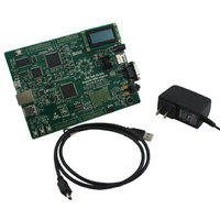
Board, Cable, Documentation, Power Supply
For Use With/related Products
SH7216
Lead Free Status / RoHS Status
Lead free / RoHS Compliant


6.3. LEDs
There are 19 LEDs on the RDK board. The green ‘POWER’ LED (LED16) lights when the board is powered. The E10A
Debugger Interface has an LED (LED15) that illuminates when the Debugger USB Interface is connected to a host PC.
A tri-color LED (Red/Green/Blue – D5) is provided as are the 12 user LEDs (LED1 – LED12) are connected to an IO port
and will light when their corresponding port pin is set low. The 12 user LEDs are arranged to show the winding phases
of the motor control circuit. The remaining 4 LEDs (LED13, LED14, and 2 LEDs on the RJ-45) are Ethernet specific, and
are not accessed directly from the MCU.
Table 6-3, below, shows the user LED pin references and their corresponding microcontroller port pin connections.
Table 6-2 shows the pin allocation and signal names used on this connector.
Pin
1
3
5
7
9
11
13
Ground
No Connection
R/W (Wired to Write only)
No Connection
No Connection
DLCDD4 (PE0)
DLCDD6 (PE2)
Circuit Net Name
Table 6-2: Debug LCD Module Connections
-
-
-
-
-
176
2
Device
Pin
LCD1
2
4
6
8
10
12
14
Pin
10
5VCC
DLCDRS (PB9)
DLCDE + 47k pull down to ground (PB14)
No connection
No connection
DLCDD5 (PE1)
DLCDD7 (PE3)
Circuit Net Name
-
53
116
-
-
1
3
Device
Pin
Related parts for YRDKSH7216
Image
Part Number
Description
Manufacturer
Datasheet
Request
R

Part Number:
Description:
KIT STARTER FOR M16C/29
Manufacturer:
Renesas Electronics America
Datasheet:

Part Number:
Description:
KIT STARTER FOR R8C/2D
Manufacturer:
Renesas Electronics America
Datasheet:

Part Number:
Description:
R0K33062P STARTER KIT
Manufacturer:
Renesas Electronics America
Datasheet:

Part Number:
Description:
KIT STARTER FOR R8C/23 E8A
Manufacturer:
Renesas Electronics America
Datasheet:

Part Number:
Description:
KIT STARTER FOR R8C/25
Manufacturer:
Renesas Electronics America
Datasheet:

Part Number:
Description:
KIT STARTER H8S2456 SHARPE DSPLY
Manufacturer:
Renesas Electronics America
Datasheet:

Part Number:
Description:
KIT STARTER FOR R8C38C
Manufacturer:
Renesas Electronics America
Datasheet:

Part Number:
Description:
KIT STARTER FOR R8C35C
Manufacturer:
Renesas Electronics America
Datasheet:

Part Number:
Description:
KIT STARTER FOR R8CL3AC+LCD APPS
Manufacturer:
Renesas Electronics America
Datasheet:
Part Number:
Description:
KIT STARTER FOR RX610
Manufacturer:
Renesas Electronics America
Datasheet:

Part Number:
Description:
KIT STARTER FOR R32C/118
Manufacturer:
Renesas Electronics America
Datasheet:

Part Number:
Description:
KIT DEV RSK-R8C/26-29
Manufacturer:
Renesas Electronics America
Datasheet:

Part Number:
Description:
KIT STARTER FOR SH7124
Manufacturer:
Renesas Electronics America
Datasheet:

Part Number:
Description:
KIT STARTER FOR H8SX/1622
Manufacturer:
Renesas Electronics America
Datasheet:

Part Number:
Description:
KIT DEV FOR SH7203
Manufacturer:
Renesas Electronics America
Datasheet: