AT91SAM7XC-EK Atmel, AT91SAM7XC-EK Datasheet
AT91SAM7XC-EK
Specifications of AT91SAM7XC-EK


Related parts for AT91SAM7XC-EK


AT91SAM7XC-EK Summary of contents
Page 1
... AT91SAM7X-EK Evaluation Board for AT91SAM7X and AT91SAM7XC .............................................................................................. User Guide ...
Page 2
AT91SAM7X-EK Evaluation Board User Guide ...
Page 3
... AT91SAM7X-EK Block Diagram ...............................................................2-4 Section 3 Board Description ................................................................................. 3-1 3.1 AT91SAM7X Microcontroller.....................................................................3-1 3.2 AT91SAM7X Block Diagram .....................................................................3-4 3.3 AT91SAM7XC Microcontroller ..................................................................3-5 3.4 AT91SAM7XC Export Regulations Statement ..........................................3-7 3.5 AT91SAM7XC Block Diagram ..................................................................3-8 3.6 Memory .....................................................................................................3-9 3.7 Clock Circuitry ...........................................................................................3-9 3.8 Reset Circuitry ..........................................................................................3-9 3.9 Power Supply Circuitry ...
Page 4
Section 6 Errata .................................................................................................... 6-1 6.1 Errata ........................................................................................................6-1 Section 7 Revision History.................................................................................... 7-1 7.1 Revision History ........................................................................................7-1 AT91SAM7X-EK Evaluation Board User Guide ...
Page 5
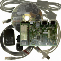
... The AT91SAM7X- EK Evaluation Board AT91SAM7X-EK Evaluation Board User Guide The AT91SAM7X-EK and the AT91SAM7XC-EK evaluation kits enable evaluation capa- bilities and code development of applications running on the AT91SAM7X or the AT91SAM7XC microcontroller. This guide focuses on the AT91SAM7X-EK board as a common evaluation platform for the AT91SAM7X and AT91SAM7XC devices in a 100-lead LQFP package ...
Page 6
... Overview 1-2 6195E–ATARM–22-Mar-07 ! Power LED and general-purpose LEDs ! DataFlash ® card slot ! expansion connector ! Atmel ® serial DataFlash ! One footprint for Atmel Serial EEPROM (MN11) AT91SAM7X-EK Evaluation Board User Guide ...
Page 7
Electrostatic Warning 2.2 Requirements AT91SAM7X-EK Evaluation Board User Guide Setting Up the AT91SAM7X-EK The AT91SAM7X-EK evaluation board is shipped in a protective anti-static package. The board must not be subjected to high electrostatic potentials. A grounding strap or similar ...
Page 8
Setting Up the AT91SAM7X-EK Evaluation Board 2.3 Layout Figure 2-1. Layout - Top View 2-2 6195E–ATARM–22-Mar-07 AT91SAM7X-EK Evaluation Board User Guide ...
Page 9
... The AT91SAM7X-EK evaluation board is delivered with a DVD-ROM containing all nec- essary information and step-by-step procedures for working with the most common development tool chains. Please refer to this DVD-ROM the AT91 web site, http://www.atmel.com/products/AT91/, for the most up-to-date information on getting started with the evaluation kit. Setting Up the AT91SAM7X-EK Evaluation Board 6195E– ...
Page 10
... XOUT XIN EXT CLK INPUT JTAG/ICE CONNECTOR 2-4 6195E–ATARM–22-Mar-07 DATAFLASH CARD READER RS232 NRST SERIAL DATAFLASH MANUAL RESET CAN AT91SAM7X256 AT91SAM7XC256 (LQFP100) ADC PIO B JTAG/ICE 3.3VANA GNDANA 3.00V +- 0.2% EXTERNAL REF 1 ANALOG INPUT DBGU USB DEVICE ETHERNET 10/100 RS232 ...
Page 11
AT91SAM7X Microcontroller AT91SAM7X-EK Evaluation Board User Guide ® ! Incorporates the ARM7TDMI ARM – High-performance 32-bit RISC Architecture – High-density 16-bit Instruction Set – Leader in MIPS/Watt ™ – EmbeddedICE , Debug Communication Channel Support ! Internal High-speed Flash ...
Page 12
Board Description 3-2 6195E–ATARM–22-Mar-07 – Power Optimization Capabilities, Including Slow Clock Mode (Down to 500 Hz) and Idle Mode – Four Programmable External Clock Signals ! Advanced Interrupt Controller (AIC) – Individually Maskable, Eight-level Priority, Vectored Interrupt Sources – Two ...
Page 13
... Double PWM Generation, Capture/Waveform Mode, Up/Down Capability ! One Four-channel 16-bit Power Width Modulation Controller (PWMC) ! One Two-wire Interface (TWI) – Master Mode Support Only, All Two-wire Atmel EEPROMs Supported ! One 8-channel 10-bit Analog-to-Digital Converter, Four Channels Multiplexed with Digital I/Os ! SAM-BA ™ ...
Page 14
Board Description 3.2 AT91SAM7X Block Diagram 3-4 6195E–ATARM–22-Mar-07 Figure 3-1. Block Diagram TDI TDO ICE JTAG TMS SCAN TCK JTAGSEL System Controller TST FIQ AIC IRQ0-IRQ1 PDC DRXD DBGU DTXD PDC PCK0-PCK3 PLLRC PLL XIN PMC OSC XOUT RCOSC VDDCORE ...
Page 15
... EmbeddedICE , Debug Communication Channel Support ! Internal High-speed Flash – 256 Kbytes (AT91SAM7XC256) Organized in 1024 Pages of 256 Bytes – 128 Kbytes (AT91SAM7XC128) Organized in 512 Pages of 256 Bytes – Single Cycle Access MHz in Worst Case Conditions – Prefetch Buffer Optimizing Thumb Instruction Execution at Maximum Speed – ...
Page 16
Board Description 3-6 6195E–ATARM–22-Mar-07 – 12-bit key-protected Programmable Counter – Provides Reset or Interrupt Signals to the System – Counter May Be Stopped While the Processor is in Debug State or in Idle Mode ! Real-time Timer (RTT) – 32-bit ...
Page 17
... AT91SAM7XC Export Regulations Statement AT91SAM7X-EK Evaluation Board User Guide – 16-bit Programmable Data Length, Four External Peripheral Chip Selects ! One Three-channel 16-bit Timer/Counter (TC) – Three External Clock Inputs, Two Multi-purpose I/O Pins per Channel – Double PWM Generation, Capture/Waveform Mode, Up/Down Capability ...
Page 18
... Board Description 3.5 AT91SAM7XC Block Diagram 3-8 6195E–ATARM–22-Mar-07 Figure 3-2. Block Diagram TDI TDO ICE JTAG TMS SCAN TCK JTAGSEL System Controller TST FIQ AIC IRQ0-IRQ1 PDC DRXD DBGU DTXD PDC PCK0-PCK3 PLLRC PLL XIN PMC OSC XOUT RCOSC ...
Page 19
... Kbytes of Internal High-speed Flash ! 64 Kbytes of Internal High-speed SRAM ! Atmel serial DataFlash ® ! One footprint for Atmel Serial EEPROM memory. The user can fit an AT24C128AN or AT24C256AN or AT24C512AN in 8S1 package as well as a cryptomemory AT88C25616C-SI ! 18.432 MHz standard crystal for the embedded oscillator ...
Page 20
... DBGU serial RS232 COM Port ! One DataFlash card slot ! All I/Os of the AT91SAM7X and the AT91SAM7XC are routed to peripheral extension connectors (J16). This allows the developer to check the integrity of the components and to extend the features of the board by adding external hardware components or boards ...
Page 21
Configuration Straps AT91SAM7X-EK Evaluation Board User Guide Table 4-1. Configuration Jumpers and Straps Default Designation Setting J8 Opened Erases all internal Flash memory when the board is powered that, the user will have to close the J8 ...
Page 22
Configuration Straps 4-2 6195E–ATARM–22-Mar-07 Table 4-1. Configuration Jumpers and Straps (Continued) Default Designation Setting Closed Enables the use of 18.432MHz crystal. Must be open if an external clock is used. S6 Closed Enables the Power Led control ...
Page 23
Schematics AT91SAM7X-EK Evaluation Board User Guide This section contains the following schematics: ! Processor Board ! I/O ! Ethernet ! RF modules Section 5 Schematics 5-1 6195E–ATARM–22-Mar-07 ...
Page 24
... AT91SAM7X-EK AT91SAM7X-EK NOT POPULATED AT91SAM7XC-EK AT91SAM7XC-EK AT91SAM7XC-EK PROCESSOR BOARD PROCESSOR BOARD PROCESSOR BOARD This agreement is our property. Reproduction and publication without our written authorization shall expose offender to legal proceedings. This agreement is our property. Reproduction and publication without our written authorization shall expose offender to legal proceedings. ...
Page 25
... AT91SAM7X-EK AT91SAM7XC-EK AT91SAM7XC-EK AT91SAM7XC-EK This agreement is our property. Reproduction and publication without our written authorization shall expose offender to legal proceedings. This agreement is our property. Reproduction and publication without our written authorization shall expose offender to legal proceedings. This agreement is our property. Reproduction and publication without our written authorization shall expose offender to legal proceedings. ...
Page 26
... AT91SAM7X-EK AT91SAM7X-EK AT91SAM7X-EK AT91SAM7XC-EK AT91SAM7XC-EK AT91SAM7XC-EK ETHERNET ETHERNET ETHERNET This agreement is our property. Reproduction and publication without our written authorization shall expose offender to legal proceedings. This agreement is our property. Reproduction and publication without our written authorization shall expose offender to legal proceedings. ...
Page 27
... AT91SAM7X-EK AT91SAM7X-EK AT91SAM7X-EK AT91SAM7XC-EK AT91SAM7XC-EK AT91SAM7XC-EK RF MODULES RF MODULES RF MODULES This agreement is our property. Reproduction and publication without our written authorization shall expose offender to legal proceedings. This agreement is our property. Reproduction and publication without our written authorization shall expose offender to legal proceedings. ...
Page 28
Schematics 5-2 6195E–ATARM–22-Mar-07 AT91SAM7X-EK Evaluation Board User Guide ...
Page 29
DM9161A Ethernet Phy Connections 6.2 TWI line pullups for Fast Mode operation AT91SAM7X-EK Evaluation Board User Guide The Ethernet interface works as presented in the schematics, but the connections are not in compliance with Davicom recommendations. To comply with ...
Page 30
Errata 6-2 6195E–ATARM–22-Mar-07 AT91SAM7X-EK Evaluation Board User Guide ...
Page 31
... First issue. Figure 2-3 6195B Updated functionalities. New board block diagram and schematics issued. 6195C Updated document to contain new product AT91SAM7XC. Added new section with Errata. 6195D Removed references to 32 Mbit serial DataFlash (AT45DB321C-CNC) in Section 3.6 and in 6195E Added Errata AT91SAM7X-EK Evaluation Board User Guide with new signal names ...
Page 32
Revision History 7-2 6195E–ATARM–22-Mar-07 AT91SAM7X-EK Evaluation Board User Guide ...
Page 33
... Disclaimer: The information in this document is provided in connection with Atmel products. No license, express or implied, by estoppel or otherwise, to any intellectual property right is granted by this document or in connection with the sale of Atmel products. EXCEPT AS SET FORTH IN ATMEL’S TERMS AND CONDI- TIONS OF SALE LOCATED ON ATMEL’S WEB SITE, ATMEL ASSUMES NO LIABILITY WHATSOEVER AND DISCLAIMS ANY EXPRESS, IMPLIED OR STATUTORY WARRANTY RELATING TO ITS PRODUCTS INCLUDING, BUT NOT LIMITED TO, THE IMPLIED WARRANTY OF MERCHANTABILITY, FITNESS FOR A PARTICULAR PURPOSE, OR NON-INFRINGEMENT ...