AT91SAM7XC-EK Atmel, AT91SAM7XC-EK Datasheet - Page 29
AT91SAM7XC-EK
Manufacturer Part Number
AT91SAM7XC-EK
Description
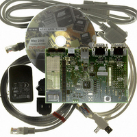
KIT EVAL FOR AT91SAM7XC256/128
Manufacturer
Atmel
Series
AT91SAM Smart ARMr
Type
MCUr
Specifications of AT91SAM7XC-EK
Contents
Evaluation Board, Parallel Cable and CD-ROM
Processor To Be Evaluated
AT91SAM7XCx
Data Bus Width
32 bit
Interface Type
RS-232, Ethernet, USB
For Use With/related Products
AT91SAM7XC256, AT91SAM7XC128
Lead Free Status / RoHS Status
Contains lead / RoHS non-compliant


6.1
6.2
AT91SAM7X-EK Evaluation Board User Guide
DM9161A
Ethernet Phy
Connections
TWI line pullups
for Fast Mode
operation
The Ethernet interface works as presented in the schematics, but the connections are
not in compliance with Davicom recommendations.
To comply with Davicom recommendations on connecting this device, J27-4 and J27-5
(RJ45 connector, CT) should be connected to the VCCA side of L2. In the current sche-
matics (ETHERNET, Sheet 3/4), the VCCA side of L2 is connected to MN10-1 and
MN10-2 (DM9161A, AVDDR).
For additional information, refer to the Davicom datasheet for DM9161A and associated
Application Notes available on http://www.davicom.com.tw/.
In order to use the TWI in Fast Mode (up to 400 Kbits/s), the default 10 K resistors R38
and R39 should be replaced by smaller values (e.g., 2.2 K ).
Note that there is no need to change the pull-up resistors if the TWI is used in Standard
Mode (up to 100 Kbits/s).
Section 6
6195E–ATARM–22-Mar-07
Errata
6-1
Related parts for AT91SAM7XC-EK
Image
Part Number
Description
Manufacturer
Datasheet
Request
R

Part Number:
Description:
MCU ARM9 64K SRAM 144-LFBGA
Manufacturer:
Atmel
Datasheet:

Part Number:
Description:
IC ARM7 MCU FLASH 256K 100LQFP
Manufacturer:
Atmel
Datasheet:

Part Number:
Description:
IC ARM9 MPU 217-LFBGA
Manufacturer:
Atmel
Datasheet:
Part Number:
Description:
MCU ARM9 ULTRA LOW PWR 217-LFBGA
Manufacturer:
Atmel
Datasheet:

Part Number:
Description:
MCU ARM9 324-TFBGA
Manufacturer:
Atmel
Datasheet:
Part Number:
Description:
IC MCU ARM9 SAMPLING 217CBGA
Manufacturer:
Atmel
Datasheet:
Part Number:
Description:
IC ARM9 MCU 217-LFBGA
Manufacturer:
Atmel
Datasheet:

Part Number:
Description:
IC ARM9 MCU 208-PQFP
Manufacturer:
Atmel
Datasheet:
Part Number:
Description:
MCU ARM 512K HS FLASH 100-LQFP
Manufacturer:
Atmel
Datasheet:

Part Number:
Description:
MCU ARM 512K HS FLASH 100-TFBGA
Manufacturer:
Atmel
Datasheet:
Part Number:
Description:
IC ARM9 MCU 200 MHZ 324-TFBGA
Manufacturer:
Atmel
Datasheet:

Part Number:
Description:
IC ARM MCU 16BIT 128K 256BGA
Manufacturer:
Atmel
Datasheet:

Part Number:
Description:
IC ARM7 MCU 32BIT 128K 64LQFP
Manufacturer:
Atmel
Datasheet:

Part Number:
Description:
IC ARM7 MCU FLASH 256K 128-LQFP
Manufacturer:
Atmel
Datasheet:
Part Number:
Description:
IC ARM7 MCU FLASH 512K 128-LQFP
Manufacturer:
Atmel
Datasheet: