AT91SAM7XC-EK Atmel, AT91SAM7XC-EK Datasheet - Page 22
AT91SAM7XC-EK
Manufacturer Part Number
AT91SAM7XC-EK
Description
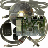
KIT EVAL FOR AT91SAM7XC256/128
Manufacturer
Atmel
Series
AT91SAM Smart ARMr
Type
MCUr
Specifications of AT91SAM7XC-EK
Contents
Evaluation Board, Parallel Cable and CD-ROM
Processor To Be Evaluated
AT91SAM7XCx
Data Bus Width
32 bit
Interface Type
RS-232, Ethernet, USB
For Use With/related Products
AT91SAM7XC256, AT91SAM7XC128
Lead Free Status / RoHS Status
Contains lead / RoHS non-compliant


6195E–ATARM–22-Mar-07
Configuration Straps
4-2
Table 4-1. Configuration Jumpers and Straps (Continued)
Note:
Designation
S4 - S5
S10
S11
S12
S13
S14
S15
S16
S17
S18
S19
S20
S21
S22
S23
S24
S25
S26
S27
S28
S29
TP1
TP2
S6
S7
S8
S9
1. These jumpers are provided for measuring power consumption. By default, they are
closed. To use this feature, the user has to open the strap and insert an anmeter.
Opened
Opened
Opened
Opened
Opened
Default
Setting
Closed
Closed
Closed
Closed
Closed
Closed
Closed
Closed
Closed
Closed
Closed
Closed
Closed
Closed
Closed
Closed
Closed
Closed
Closed
Closed
N.A
N.A
Enables the use of 18.432MHz crystal. Must be open if an
external clock is used.
Enables the Power Led control (PB25).
Disables Serial DataFlash write protect.
Enables the use of the TXD CAN transceiver (PA20)
Enables the use of the RXD CAN transceiver (PA19)
Enables control of the Standby/Normal mode for CAN
transceivers (PA2)
Enables control of the Standby/Normal mode for CAN
transceivers (PA2).
If S11 is closed, S10 must be open.
Enables the use of PWM3 Analog Output (PB30)
Enables the use of the TXD0 signal (PA1)
Enables the use of the RTS0 signal (PA3)
Enables the use of the RXD0 signal (PA0)
Enables the use of the CTS0 signal (PA4)
Enables the use of the User LED DS1 (PB19)
Enables the use of the User LED DS2 (PB20)
Enables the use of the User LED DS3 (PB21)
Enables the use of the User LED DS4 (PB22)
Enables the use of the DBGU TXD signal (PA28)
Enables the use of the DBGU RXD signal (PA27)
ETHERNET MII is the default mode. To evaluate the RMII
mode, the user change S23 to S26 configuration in the
following way: S23 Closed, S24 Opened, S25 Closed, S26
Opened
Reserved
Enables the use of the SCL of MN11 (PA11)
Enables the use of the SDA of MN11 (PA10)
GND Test point.
GND Test point.
AT91SAM7X-EK Evaluation Board User Guide
Feature
Related parts for AT91SAM7XC-EK
Image
Part Number
Description
Manufacturer
Datasheet
Request
R

Part Number:
Description:
MCU ARM9 64K SRAM 144-LFBGA
Manufacturer:
Atmel
Datasheet:

Part Number:
Description:
IC ARM7 MCU FLASH 256K 100LQFP
Manufacturer:
Atmel
Datasheet:

Part Number:
Description:
IC ARM9 MPU 217-LFBGA
Manufacturer:
Atmel
Datasheet:
Part Number:
Description:
MCU ARM9 ULTRA LOW PWR 217-LFBGA
Manufacturer:
Atmel
Datasheet:

Part Number:
Description:
MCU ARM9 324-TFBGA
Manufacturer:
Atmel
Datasheet:
Part Number:
Description:
IC MCU ARM9 SAMPLING 217CBGA
Manufacturer:
Atmel
Datasheet:
Part Number:
Description:
IC ARM9 MCU 217-LFBGA
Manufacturer:
Atmel
Datasheet:

Part Number:
Description:
IC ARM9 MCU 208-PQFP
Manufacturer:
Atmel
Datasheet:
Part Number:
Description:
MCU ARM 512K HS FLASH 100-LQFP
Manufacturer:
Atmel
Datasheet:

Part Number:
Description:
MCU ARM 512K HS FLASH 100-TFBGA
Manufacturer:
Atmel
Datasheet:
Part Number:
Description:
IC ARM9 MCU 200 MHZ 324-TFBGA
Manufacturer:
Atmel
Datasheet:

Part Number:
Description:
IC ARM MCU 16BIT 128K 256BGA
Manufacturer:
Atmel
Datasheet:

Part Number:
Description:
IC ARM7 MCU 32BIT 128K 64LQFP
Manufacturer:
Atmel
Datasheet:

Part Number:
Description:
IC ARM7 MCU FLASH 256K 128-LQFP
Manufacturer:
Atmel
Datasheet:
Part Number:
Description:
IC ARM7 MCU FLASH 512K 128-LQFP
Manufacturer:
Atmel
Datasheet: