ST7MDT20-DVP3 STMicroelectronics, ST7MDT20-DVP3 Datasheet - Page 17
ST7MDT20-DVP3
Manufacturer Part Number
ST7MDT20-DVP3
Description
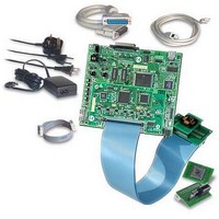
KIT EMULATOR FOR ST72321/324/521
Manufacturer
STMicroelectronics
Series
ST7-DVP3r
Type
Microcontrollerr
Datasheets
1.ST7MDT10-8DVP.pdf
(3 pages)
2.ST7MDT10-8DVP.pdf
(44 pages)
3.ST7MDT20-TEBDVP.pdf
(38 pages)
Specifications of ST7MDT20-DVP3
Contents
Main Emulation Board (MEB), Target Emulation Board (TEB), Cables, Power Supply and Documentation
For Use With/related Products
ST72321, ST72324, ST72521
Lead Free Status / RoHS Status
Lead free / RoHS Compliant
Other names
497-4874


ST7-DVP3 Emulator User Manual
4.3
4.3.1
4.3.2
Hardware features
While target emulation boards will vary from one version to another, all ST7-DVP3
development boards offer some standard features that will help you debug your
application, including voltage selection, analyzer probe input pins, input/output
triggers
characteristics of the ST7-DVP3 development board are described in this section.
Emulation status LEDs
There are three LEDs on the ST7-DVP3 development board, which indicate
emulator status during debugging (see
•
•
•
Power supply
The emulator’s power supply plugs into the power supply connector on the MEB
(see
Voltage selection
3 Analyzer probe
Reset (Red) — indicates that the emulator is being reset, or flashes slowly
when the emulator is in Wait for Interrupt mode.
Halt (Yellow) — indicates when the emulation chip is in Halt mode.
Run (Green) — indicates when the emulator is running your application.
Red, Yellow and Green
input pins
Figure 8
Three Status LEDs:
switch
EXTCLK
and
). When you connect the power supply, be sure to:
Probe connectors
external clock connection.
Input/Output
trigger pins
Figure 8: General layout of ST7-DVP3
Figure 8
TEB
):
These features
MEB
USB Port
Emulation Configuration
and
Power Supply
connection
Parallel
Port
common
17/44
Related parts for ST7MDT20-DVP3
Image
Part Number
Description
Manufacturer
Datasheet
Request
R

Part Number:
Description:
KIT CONNECTION ST7MDT20-DVP3
Manufacturer:
STMicroelectronics
Datasheet:
Part Number:
Description:
KIT CONNECTOR FOR STMDT20 44TQFP
Manufacturer:
STMicroelectronics
Datasheet:
Part Number:
Description:
BOARD TARGET EMULATION ST7-DVP
Manufacturer:
STMicroelectronics
Datasheet:
Part Number:
Description:
KIT CONNECTOR FOR STMDT20 80TQFP
Manufacturer:
STMicroelectronics
Datasheet:
Part Number:
Description:
KIT CONNECTOR FOR STMDT20 32TQFP
Manufacturer:
STMicroelectronics
Datasheet:
Part Number:
Description:
KIT CONNECTOR FOR STMDT20 64TQFP
Manufacturer:
STMicroelectronics
Datasheet:
Part Number:
Description:
BOARD EVALUATION/TRAINING/PROGRM
Manufacturer:
STMicroelectronics
Datasheet:
Part Number:
Description:
BOARD EVALUATION/TRAINING/PROGRM
Manufacturer:
STMicroelectronics
Datasheet:
Part Number:
Description:
BOARD PROGRAMMING SGL POS ST7
Manufacturer:
STMicroelectronics
Datasheet:
Part Number:
Description:
KIT DEVELOPMENT ST7
Manufacturer:
STMicroelectronics
Datasheet:

Part Number:
Description:
Low Cost, Real Time Emulator Series for ST7
Manufacturer:
STMICROELECTRONICS [STMicroelectronics]
Datasheet:
Part Number:
Description:
Full-featured, real time emulator series for ST7
Manufacturer:
STMICROELECTRONICS [STMicroelectronics]
Datasheet:
Part Number:
Description:
Programming board
Manufacturer:
STMICROELECTRONICS [STMicroelectronics]
Datasheet:
Part Number:
Description:
8-bit microcontroller with single voltage Flash memory, data EEPROM, ADC, timers, SPI
Manufacturer:
STMICROELECTRONICS [STMicroelectronics]
Datasheet:
Part Number:
Description:
In-Circuit Programmer
Manufacturer:
STMicroelectronics
Datasheet: