ST7MDT20-DVP3 STMicroelectronics, ST7MDT20-DVP3 Datasheet - Page 18
ST7MDT20-DVP3
Manufacturer Part Number
ST7MDT20-DVP3
Description
KIT EMULATOR FOR ST72321/324/521
Manufacturer
STMicroelectronics
Series
ST7-DVP3r
Type
Microcontrollerr
Datasheets
1.ST7MDT10-8DVP.pdf
(3 pages)
2.ST7MDT10-8DVP.pdf
(44 pages)
3.ST7MDT20-TEBDVP.pdf
(38 pages)
Specifications of ST7MDT20-DVP3
Contents
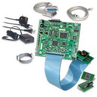
Main Emulation Board (MEB), Target Emulation Board (TEB), Cables, Power Supply and Documentation
For Use With/related Products
ST72321, ST72324, ST72521
Lead Free Status / RoHS Status
Lead free / RoHS Compliant
Other names
497-4874


Emulation Configuration
4.3.3
Caution:
18/44
1 Ensure that the operating voltage of the ST7-DVP3 emulator (110 Volts/
2 Install the provided ferrite clip on the cord running between the emulator and the
3 Plug the power supply into the mains using the supply cable provided.
Application voltage selector switch
Before you connect your application board to your emulator, you must set the
operating voltage to that which corresponds to the designed operating voltage of
your application board. This is done with the voltage selector switch. The switch is
located on the main emulation board near the status LEDs (see
you to select an operating voltage of either 3.3V or 5V.
Failure to select the correct voltage for your application board can result in damage to your
emulator or your application board.
220 Volts) matches that which is indicated on the label of your power supply.
Contact your dealer if this voltage does not correspond to your mains.
power supply, approximately 10 cm from your emulator (see
3
Figure 9: Connecting the ferrite clip
10 cm
2
1
ST7-DVP3 Emulator User Manual
Power cable
Ferrite
Figure 8
Figure 9
ST7-DVP3 emulator
). It allows
).
Related parts for ST7MDT20-DVP3
Image
Part Number
Description
Manufacturer
Datasheet
Request
R

Part Number:
Description:
KIT CONNECTION ST7MDT20-DVP3
Manufacturer:
STMicroelectronics
Datasheet:
Part Number:
Description:
KIT CONNECTOR FOR STMDT20 44TQFP
Manufacturer:
STMicroelectronics
Datasheet:
Part Number:
Description:
BOARD TARGET EMULATION ST7-DVP
Manufacturer:
STMicroelectronics
Datasheet:
Part Number:
Description:
KIT CONNECTOR FOR STMDT20 80TQFP
Manufacturer:
STMicroelectronics
Datasheet:
Part Number:
Description:
KIT CONNECTOR FOR STMDT20 32TQFP
Manufacturer:
STMicroelectronics
Datasheet:
Part Number:
Description:
KIT CONNECTOR FOR STMDT20 64TQFP
Manufacturer:
STMicroelectronics
Datasheet:
Part Number:
Description:
BOARD EVALUATION/TRAINING/PROGRM
Manufacturer:
STMicroelectronics
Datasheet:
Part Number:
Description:
BOARD EVALUATION/TRAINING/PROGRM
Manufacturer:
STMicroelectronics
Datasheet:
Part Number:
Description:
BOARD PROGRAMMING SGL POS ST7
Manufacturer:
STMicroelectronics
Datasheet:
Part Number:
Description:
KIT DEVELOPMENT ST7
Manufacturer:
STMicroelectronics
Datasheet:

Part Number:
Description:
Low Cost, Real Time Emulator Series for ST7
Manufacturer:
STMICROELECTRONICS [STMicroelectronics]
Datasheet:
Part Number:
Description:
Full-featured, real time emulator series for ST7
Manufacturer:
STMICROELECTRONICS [STMicroelectronics]
Datasheet:
Part Number:
Description:
Programming board
Manufacturer:
STMICROELECTRONICS [STMicroelectronics]
Datasheet:
Part Number:
Description:
8-bit microcontroller with single voltage Flash memory, data EEPROM, ADC, timers, SPI
Manufacturer:
STMICROELECTRONICS [STMicroelectronics]
Datasheet:
Part Number:
Description:
In-Circuit Programmer
Manufacturer:
STMicroelectronics
Datasheet: