NBSG111BAEVB ON Semiconductor, NBSG111BAEVB Datasheet - Page 4
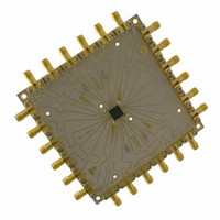
NBSG111BAEVB
Manufacturer Part Number
NBSG111BAEVB
Description
BOARD EVALUATION BBG NBSG111BA
Manufacturer
ON Semiconductor
Specifications of NBSG111BAEVB
Main Purpose
Clock/Data Driver
Utilized Ic / Part
NBSG111
Primary Attributes
W/RSECL Outputs
Technology Type
Evaluation Board
Lead Free Status / RoHS Status
Contains lead / RoHS non-compliant
For Use With/related Products
NBSG111
Other names
NBSG111BAEVB
NBSG111BAEVBOS
NBSG111BAEVBOS


Setup
Step 1:
Table 2. Basic Equipment
3. Equipment used to generate example measurements.
Power Supply with 2 outputs
Vector Network Analyzer (VNA)
180 Hybrid Coupler
Bias Tee with 50 W Resistor Termination
Matched high speed cables with SMA connectors
Power Supply cables with clips
NOTE:
Connect Power
1a: Three power levels must be provided to the board for V
face mount clips. Using the split power supply mode, GND = V
For frequency domain measurements, 2.5 V power supply is not recommended because
additional equipment (bias tee, etc.) is needed for proper operation. The input signal has to be
properly offset to meet V
Description
Setup for Frequency Domain Measurements
V
3.3 V Setup
V
V
EE
CC
TT
= −1.3 V
= 2.0 V
= GND
IHCMR
Power Supply Connections
range of the device
NBSG111BAEVB
http://onsemi.com
4
HP 6624A
R&S ZVK (10 MHz to 40 GHz)
Krytar Model #4010180
Picosecond Model #5542−219
Storm, Semflex
Example Equipment (Note 3)
.
V
2.5 V Setup
V
V
EE
CC
TT
CC
= −0.5 V
= 2.0 V
= GND
, V
TT
EE
, and GND via the sur-
= V
CC
– 2.0 V.
Qty.
1
1
1
1
3
3
Related parts for NBSG111BAEVB
Image
Part Number
Description
Manufacturer
Datasheet
Request
R

Part Number:
Description:
2.5v/3.3v Sige Differential 1 10 Clock/data Driver With Rsecl Outputs
Manufacturer:
ON Semiconductor
Datasheet:
Part Number:
Description:
ON Semiconductor [VOLTAGE REGULATOR]
Manufacturer:
ON Semiconductor
Datasheet:
Part Number:
Description:
357-036-542-201 CARDEDGE 36POS DL .156 BLK LOPRO
Manufacturer:
ON Semiconductor
Datasheet:
Part Number:
Description:
357-036-542-201 CARDEDGE 36POS DL .156 BLK LOPRO
Manufacturer:
ON Semiconductor
Datasheet:
Part Number:
Description:
357-036-542-201 CARDEDGE 36POS DL .156 BLK LOPRO
Manufacturer:
ON Semiconductor
Datasheet:
Part Number:
Description:
357-036-542-201 CARDEDGE 36POS DL .156 BLK LOPRO
Manufacturer:
ON Semiconductor
Datasheet:
Part Number:
Description:
357-036-542-201 CARDEDGE 36POS DL .156 BLK LOPRO
Manufacturer:
ON Semiconductor
Datasheet:
Part Number:
Description:
357-036-542-201 CARDEDGE 36POS DL .156 BLK LOPRO
Manufacturer:
ON Semiconductor
Datasheet:
Part Number:
Description:
357-036-542-201 CARDEDGE 36POS DL .156 BLK LOPRO
Manufacturer:
ON Semiconductor
Datasheet:
Part Number:
Description:
357-036-542-201 CARDEDGE 36POS DL .156 BLK LOPRO
Manufacturer:
ON Semiconductor
Datasheet:
Part Number:
Description:
357-036-542-201 CARDEDGE 36POS DL .156 BLK LOPRO
Manufacturer:
ON Semiconductor
Datasheet:
Part Number:
Description:
357-036-542-201 CARDEDGE 36POS DL .156 BLK LOPRO
Manufacturer:
ON Semiconductor
Datasheet:
Part Number:
Description:
Manufacturer:
ON Semiconductor
Datasheet:
Part Number:
Description:
Manufacturer:
ON Semiconductor
Datasheet: