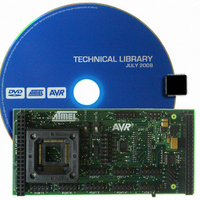
ATSTK503 Atmel, ATSTK503 Datasheet - Page 15

ATSTK503
Manufacturer Part Number
ATSTK503
Description
STARTER KIT AVR EXP MODULE 100P
Manufacturer
Atmel
Datasheet
1.ATSTK503.pdf
(17 pages)
Specifications of ATSTK503
Accessory Type
STK500 Expansion Module
Processor To Be Evaluated
Atmegaxxxx
Data Bus Width
8 bit
Interface Type
JTAG
For Use With/related Products
100-pin megaAVR Devices
For Use With
ATSTK500 - PROGRAMMER AVR STARTER KIT
Lead Free Status / RoHS Status
Lead free / RoHS Compliant
Troubleshooting Guide
Programming problems
General problems
Problem
ISP programming
does not work
ISP programming
does not work
High-Voltage
programming does
not work.
High-Voltage
programming does
not work.
High-Voltage
programming does
not work.
Problem
Some of the port pins are
not working .
The code isn't running.
The AVR will not run on x
MHz, but works ok on
lower frequencies.
The AVR will not run on x
MHz, but works ok on
lower frequencies. I have
a x MHz crystal mounted
on STK500
Cause
ISP cable is not connected Connect a 6-pin cable between the ISP6PIN
The ISP clock is to fast if
the AVR is running at a low
clock frequency.
The 10-pin cables are not
connected correctly.
The BSEL2, OSCSEL,
RESET and VTARGET
jumpers on STK500 are not
set right.
The STK504 clock switch is
in the wrong position.
Cause
The AVR is not
properly mounted in
the ZIF socket.
The AVR has
no/wrong clock
source.
The clock frequency
is exceeding the
clock rate of the AVR
(at a certain
operating voltage).
Crystals should be
placed in the crystal
socket on STK503.
Solution
Make sure the chip is properly aligned in the
socket. When the spring-loaded latch is
depressed, the chip should fit nicely into the
bottom of the socket.
According to the clock fuse setting, select the
appropriate clock source on STK500 and
STK503. Check the OSCSEL jumper on
STK500 and clock switch on STK503. If you are
using a crystal in one of the sockets, check that
it is firmly mounted in its socket.
Check that you are running the AVR within
specifications. Check the speed grade of the
AVR and consult the datasheet for operating
frequencies and voltages.
Place the crystal in the socket on STK503. Set
the clock switch to the position closest to the
crystal socket..
Solution
connector on STK500 and the ISP connector on
STK503. See also Programming the AVR.
Make sure the clock switch on STK503 is in the
right position. In the Board page of the
programming dialog in AVR Studio, try reducing
the ISP clock frequency.
See the Programming the AVR chapter for
setup.
See the Programming the AVR chapter for
setup.
Set the switch to the STK500 position. See also
Programming the AVR.
15


