ATSTK503 Atmel, ATSTK503 Datasheet - Page 4
ATSTK503
Manufacturer Part Number
ATSTK503
Description
STARTER KIT AVR EXP MODULE 100P
Manufacturer
Atmel
Datasheet
1.ATSTK503.pdf
(17 pages)
Specifications of ATSTK503
Accessory Type
STK500 Expansion Module
Processor To Be Evaluated
Atmegaxxxx
Data Bus Width
8 bit
Interface Type
JTAG
For Use With/related Products
100-pin megaAVR Devices
For Use With
ATSTK500 - PROGRAMMER AVR STARTER KIT
Lead Free Status / RoHS Status
Lead free / RoHS Compliant


Getting Started
In this chapter you will get an overview of all the features of the STK503. You will
learn how to use the STK503 with STK500 and how to mount the AVR in the ZIF
socket.
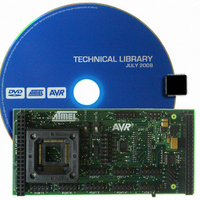
Hardware overview
The STK503 is a flexible tool to start developing and debugging applications for
100-pin AVRs as the ATmega2560. There are connectors for all available
signals, making it easy to connect to your own hardware, if required.
Figure 3-1: STK503
ZIF socket:
JTAG connector:
ISP connector:
Clock source switches:
SRAM footprint:
Here you place the AVR. See Placing the AVR for more details.
This is the connection that lets you upload and debug your application
with the JTAGICE mk II. See JTAG programming and JTAG debugging.
By mounting a cable between this connector and the programming
connector on STK500, you can easily upload new programs to the AVR.
See In-System Programming for a description on how to use AVR Studio
and how connect the cable.
The STK503 has two switches that lets you select between different on-
board and external clock sources. This is described in the Clock options
chapter.
The board has a footprint for an SRAM chip. No SRAM is mounted, so
you can select an SRAM with the right operating voltage. For more
information on using the SRAM and it connection, see the External
Memory Interface chapter.
4
Related parts for ATSTK503
Image
Part Number
Description
Manufacturer
Datasheet
Request
R

Part Number:
Description:
DEV KIT FOR AVR/AVR32
Manufacturer:
Atmel
Datasheet:

Part Number:
Description:
INTERVAL AND WIPE/WASH WIPER CONTROL IC WITH DELAY
Manufacturer:
ATMEL Corporation
Datasheet:
Part Number:
Description:
Low-Voltage Voice-Switched IC for Hands-Free Operation
Manufacturer:
ATMEL Corporation
Datasheet:
Part Number:
Description:
MONOLITHIC INTEGRATED FEATUREPHONE CIRCUIT
Manufacturer:
ATMEL Corporation
Datasheet:
Part Number:
Description:
AM-FM Receiver IC U4255BM-M
Manufacturer:
ATMEL Corporation
Datasheet:
Part Number:
Description:
Monolithic Integrated Feature Phone Circuit
Manufacturer:
ATMEL Corporation
Datasheet:
Part Number:
Description:
Multistandard Video-IF and Quasi Parallel Sound Processing
Manufacturer:
ATMEL Corporation
Datasheet:
Part Number:
Description:
High-performance EE PLD
Manufacturer:
ATMEL Corporation
Datasheet:
Part Number:
Description:
8-bit Flash Microcontroller
Manufacturer:
ATMEL Corporation
Datasheet:
Part Number:
Description:
2-Wire Serial EEPROM
Manufacturer:
ATMEL Corporation
Datasheet: