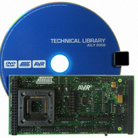
ATSTK503 Atmel, ATSTK503 Datasheet - Page 5

ATSTK503
Manufacturer Part Number
ATSTK503
Description
STARTER KIT AVR EXP MODULE 100P
Manufacturer
Atmel
Datasheet
1.ATSTK503.pdf
(17 pages)
Specifications of ATSTK503
Accessory Type
STK500 Expansion Module
Processor To Be Evaluated
Atmegaxxxx
Data Bus Width
8 bit
Interface Type
JTAG
For Use With/related Products
100-pin megaAVR Devices
For Use With
ATSTK500 - PROGRAMMER AVR STARTER KIT
Lead Free Status / RoHS Status
Lead free / RoHS Compliant
Mounting the STK503
First of all the STK503 must be mount on top of the STK500.
Figure 3-2: Mounting the STK503
Placing the AVR in the ZIF socket
The ZIF socket on STK503 takes AVRs in 100-pin TQFP packages.
ATmega3290 and ATmega6490, you must use the STK504 top module, not
To use STK500 and 100-pin AVR devices with LCD controller such as the
1.
2.
3.
4.
RAM HIGH ADDRESS jumpers:
RS-232 connector:
PORTx connectors:
Turn off power on the STK500.
Remove any other top cards.
Remove any devices from sockets of the STK500.
Place the STK503 on STK500. Make sure the EXPAND0 and EXPAND1
headers on both cards align properly.
These jumpers are for disabling some of the address lines from the
controller to the SRAM. See the External Memory Interface chapter.
The STK503 has an on-board RS-232 converter. In order to use it, you
must connect the AVR to the AVR side of the connector, and the external
RS-232 equipment (such as a PC) to the RS-232 side. See RS-232
Driver for more information.
All of the AVR ports are accessible on the port connectors. They are
marked with text corresponding to the name of the AVR port. In addition
to the port pins, they also have VCC and GND pins. See the Appendix for
pinout.
5


