ATAVRAUTO102 Atmel, ATAVRAUTO102 Datasheet
ATAVRAUTO102
Specifications of ATAVRAUTO102


Related parts for ATAVRAUTO102


ATAVRAUTO102 Summary of contents
Page 1
... ATAVRAUTO102 Kit .............................................................................................. User Guide ...
Page 2
... Unpacking the system...............................................................................2-3 2.2 System Requirements...............................................................................2-3 Section 3 Using the ATAVRAUTO102.................................................................. 3-5 3.1 Using the ATAVRAUTO102 board............................................................3-5 3.2 Updating the ATAVRAUTO102 firmware ..................................................3-5 3.3 Using X-Analyser ......................................................................................3-8 Section 4 Technical specification........................................................................ 4-11 Section 5 Technical support ............................................................................... 5-12 Section 6 Complete schematics ......................................................................... 6-13 ...
Page 3
... Overview ATAVRAUTO102 User Guide Congratulations on your purchase of the ATAVRAUTO102 starter kit. This document describes the board included in the ATAVRAUTO102 starter kit dedicated to AT90CAN128 and AT90USB1287. This document describes the ATAVRAUTO102 dedicated to AT90CAN128 and AT90USB1287 AVR microcontrollers. This board is designed to allow an easy evalua- tion of the products using demonstration software ...
Page 4
... ATAVRAUTO102 features ATAVRAUTO102 User Guide The ATAVRAUTO102 provides the following features: AT90CAN128 and AT90USB1287 QFN64 AVR programming tools interface Power supply – Regulated 5V – From LIN and/or USB connector JTAG connector: – For on-chip In Situ Programming (ISP) – For on-chip debugging using JTAG ICE Serial interfaces: – ...
Page 5
... USB Mini cable 1 Getting Started 1 Automotive CD-Rom 1 AVR CD-Rom software and technical library 1 Dear customer letter The ATAVRAUTO102 board is used as a tool to analyze car networks (up to two LIN net- works and one CAN network). The minimum hardware and software PC requirements are: ® Windows 2000/XP, Windows NT4 ...
Page 6
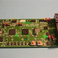
... Quick Start 2-4 7720A–AVR–06/07 The ATAVRAUTO102 board can be used to analyze up to one CAN and two LIN net- works. Connect networks (LIN and/or CAN) and plug USB cable. Figure 2-1. Board connections and default jumpers settings USB Note: At least one “VBat” should be connected to have the LIN interfaces working. ...
Page 7
... Using the ATAVRAUTO102 board 3.2 Updating the ATAVRAUTO102 firmware ATAVRAUTO102 User Guide Using the ATAVRAUTO102 The ATAVRAUTO102 can be used as a spy on a network or can act as a single Slave or Master node. LIN0 can be sniffer/slave or master. LIN1 can be sniffer or slave. CAN can be sniffer or master. ...
Page 8
... The AVR ISP is a compact and easy-to-use In-System Programming tool for developing applications with AT90CAN128. Due to the small size also an excellent tool for field upgrades of existing applications powered by the ATAVRAUTO102 and an addi- tional power supply is thus not required. The AVR ISP programming interface is integrated in AVR Studio® ...
Page 9
... PDI (PE0) and PDO (PE1). To program the device using AVR ISP programmer, connect the AVR ISP to the adaptor (ATAVRAUTO900) and connect the adaptor to the connector of the ATAVRAUTO102. Programming the ATAVRAUTO102 using ATAVRAUTO 900 The AT90CAN128 can be programmed using specific JTAG link: 3-wire debug-wire interface ...
Page 10
... Speed limitations ATAVRAUTO102 User Guide • The limitation of the USB HID Class implies a limitation if the bit rate : the maximal HID baudrate is 64 KByte/s, so 512 Kb/s. So, for a CAN Baudrate higher than 500Kb/s, a CAN load higher than 50% will imply the loss of CAN frames. ...
Page 11
... ATAVRAUTO102 User Guide Technical specification System Unit – Physical Dimensions...............................................L=92 x W=45 x H=14 mm – Weight........................................................................................................31 g Operating Conditions – Internal Voltage Supply (Flash).................................................................3.3V – Internal Voltage Supply (Micro)................................................................ 5.0V – External Voltage Supply.....................................................................7V -18V Section 4 4-11 7720A–AVR–06/07 ...
Page 12
... ATAVRAUTO102 User Guide For Technical support, please contact avr@Atmel.com. When requesting technical sup- port, please include the following information: Which target AVR device is used (complete part number) Target voltage and speed Clock source and fuse setting of the AVR Programming method (ISP, JTAG or specific Boot-Loader) Hardware revisions of the AVR tools, found on the PCB Version number of AVR Studio ...
Page 13
... ATAVRAUTO102 User Guide On the next pages, the following documents of ATAVRAUTO102 are shown: Bill of materials Complete schematics Assembly drawing Section 6 Complete schematics 6-13 7720A–AVR–06/07 ...
Page 14
... MC 0.063W 0603 1% 51K R12 56R RC22H R13 56R RC22H Q2 BC847 BC847 Q3 BCP54 BCP54-10 Q1 SI2301BDS SI2301BDS ATAVRAUTO102 User Guide Altium Limited Confidential Table 6-1. Bill of Materials Fabricant Fournisseur Code Commande Unite de Vente Phycomp FARNELL 432210 10 Phycomp FARNELL 432210 10 Phycomp FARNELL 432210 ...
Page 15
... ATAVRAUTO102 User Guide Yellow CMS LED BOOT_U AD2/PA2 49 AD1/PA1 50 AD0/PA0 51 VCC 52 GND GND 53 ADC7/TDI/PF7 TDI_U 54 ADC6/TDO/PF6 OC2B/SDA/INT1/PD1 TDO_U 55 ADC5/TMS/PF5 OC0B/SCL/INT0/PD0 TMS_U 56 ADC4/TCK/PF4 TCK_U 57 ADC3/PF3 58 ADC2/PF2 59 ADC1/PF1 60 ADC0/PF0 DF_nCS 61 AREF 62 GND GND 63 AVCC PCINT7/PC0A/OC1C/PB7 64 Complete schematics T0/PD7 32 T1/PD6 31 XCK1/PD5 30 ICP1/PD4 29 TxD1/INT3/PD3 28 RxD1/INT2/PD2 ...
Page 16
... TERM1 TERM2 BZX84-C5V1 TDI_C TDO_C TMS_C TCK_C VBAT_MEAS ATAVRAUTO102 User Guide MBR0540 MAST D_WD GND 16 TEMP LINRxD 17 PVCC 18 VCC LIN BOOT_C PA2/AD2 PD7/ CAN_SLEEP PA1/AD1 PD6/T1/RxCAN 50 31 CAN_RXD PA0/AD0 PD5/XCK1/TxCAN 51 30 CAN_TXD VCC PD4/IC1 52 29 LIN_RXD1 GND PD3/TxD1/INT3 53 28 LIN_TXD1 PF7/ADC7/TDI ...
Page 17
... ATAVRAUTO102 User Guide Complete schematics 6-17 7720A–AVR–06/07 ...
Page 18
... Disclaimer: The information in this document is provided in connection with Atmel products. No license, express or implied, by estoppel or otherwise, to any intellectual property right is granted by this document or in connection with the sale of Atmel products. EXCEPT AS SET FORTH IN ATMEL’S TERMS AND CONDI- TIONS OF SALE LOCATED ON ATMEL’S WEB SITE, ATMEL ASSUMES NO LIABILITY WHATSOEVER AND DISCLAIMS ANY EXPRESS, IMPLIED OR STATUTORY WARRANTY RELATING TO ITS PRODUCTS INCLUDING, BUT NOT LIMITED TO, THE IMPLIED WARRANTY OF MERCHANTABILITY, FITNESS FOR A PARTICULAR PURPOSE, OR NON-INFRINGEMENT ...